TERMINALS OF ECU
System information · Vehicles built from Aug 2005
| COMBINATION METER ASSEMBLY |
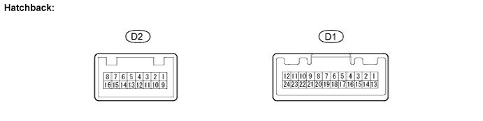

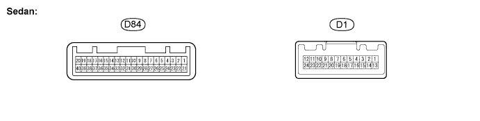
Disconnect the D1 combination meter assembly connector.
Measure the voltage and resistance of the wire harness side connector.
If the result is not as specified, there may be a malfunction in the wire harness.Standard: Symbols (Terminal No.)
Wiring Color
Terminal Description
Condition
Specified Condition
D1-1 (IG2) - Body ground
B - Body ground
Ignition switch signal
Ignition switch off → on (IG)
Below 1 V → 10 to 14 V
D1-2 (ECUB) - Body Ground
L - Body Ground
Battery
Always
10 to 14 V
D1-24 (ET) - Body Ground
BR - Body Ground
Ground
Always
Below 1 Ω
Reconnect the combination meter assembly connector.
Measure the voltage of the wire harness side connectors.
If the result is not as specified, the combination meter assembly may have a malfunction.Standard voltage: Symbols (Terminal No.)
Wiring Color
Terminal Description
Condition
Specified Condition
D1-20 (CANH) - Body ground
G -Body ground
CAN communication line
Ignition switch on (IG)
Pulse generation
D1-21 (CANL) - Body ground
W -Body ground
CAN communication line
Ignition switch on (IG)
Pulse generation
D2-9 (PBLT)*1 - Body Ground
O - Body Ground
Front passenger seat belt warning light signal (passenger side)
Ignition switch on (IG)
10 to 14 V
D2-16 (PBLT)*2 - Body Ground
O - Body Ground
Front passenger seat belt warning light signal (passenger side)
Ignition switch on (IG)
10 to 14 V
D84-9 (PBLT)*3 - Body Ground
O - Body Ground
Front passenger seat belt warning light signal (passenger side)
Ignition switch on (IG)
10 to 14 V
D1-10 (P/SB) - Body Ground
O - Body Ground
Front seat inner belt assembly signal (passenger side)
Front passenger seat is occupied and its seat belt is unfastened
Below 1 V
D1-10 (P/SB) - Body Ground
O - Body Ground
Front seat inner belt assembly signal (passenger side)
Front passenger seat is occupied and its seat belt is fastened
10 to 14 V
- HINT:
- *1: Hatchback (LHD)
- *2: Hatchback (RHD)
- *3: Sedan
- *1: Hatchback (LHD)
| MAIN BODY ECU |
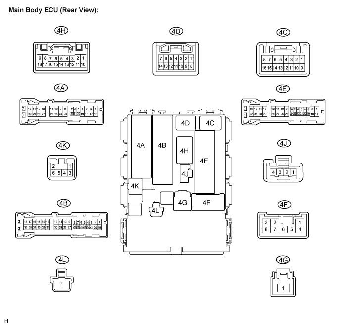
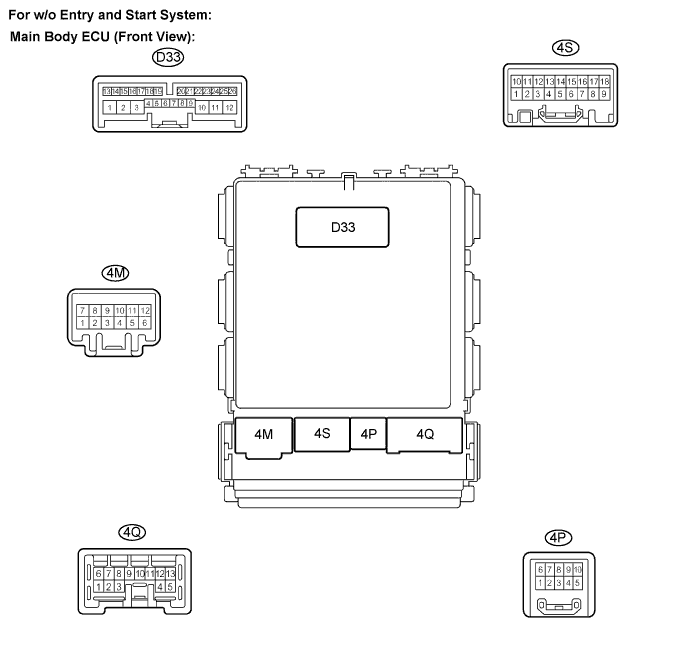
Disconnect the 4B and 4E main body ECU connectors.
Measure the voltage and resistance of the wire harness side connectors.
If the result is not as specified, there may be a malfunction in the wire harness.Standard: Symbols (Terminal No.)
Wiring Color
Terminal Description
Condition
Specified Condition
4B-30 (BECU) - 4E-17 (GND1)
L - W-B
Battery
Always
10 to 14 V
4E-17 (GND1) - Body Ground
W-B - Body Ground
Ground
Always
Below 1 Ω
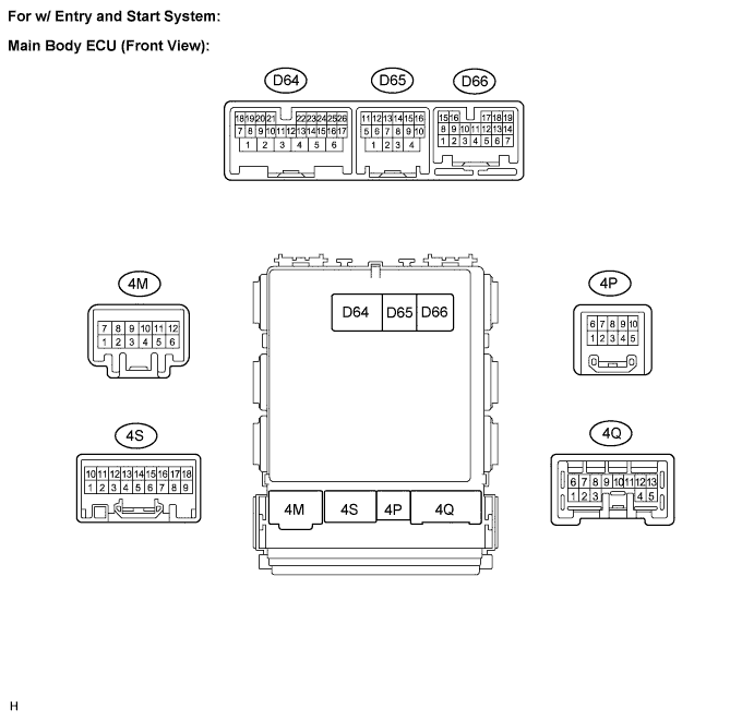
Reconnect the main body ECU connectors.
Measure the voltage of the wire harness side connectors.
Standard voltage: Symbols (Terminal No.)
Wiring Color
Terminal Description
Condition
Specified Condition
D64-26 (DBKL)*1 - Body Ground
W - Body Ground
Front seat inner belt assembly signal (driver side)
Ignition switch on (IG)
Tongue plate fastened
10 to 14 V
D64-26 (DBKL)*1 - Body Ground
W - Body Ground
Front seat inner belt assembly signal (driver side)
Ignition switch on (IG)
Tongue plate unfastened
Below 1 V
D66-15 (CANH)*1 - Body ground
R - Body ground
CAN communication line
Ignition Switch on (IG)
Pulse generation
D66-16 (CANL)*1 - Body ground
W - Body ground
CAN communication line
Ignition switch on (IG)
Pulse generation
D33-9 (DBKL)*2 - Body Ground
W - Body Ground
Front seat inner belt assembly signal (driver side)
Ignition switch on (IG)
Tongue plate fastened
10 to 14 V
D33-9 (DBKL)*2 - Body Ground
W - Body Ground
Front seat inner belt assembly signal (driver side)
Ignition switch on (IG)
Tongue plate unfastened
Below 1 V
D33-23 (CANH)*2 - Body ground
R - Body Ground
CAN communication line
Ignition switch on (IG)
Pulse generation
D33-22 (CANL)*2 - Body ground
W - Body Ground
CAN communication line
Ignition switch on (IG)
Pulse generation
4S-15*3 - Body Ground
Y - Body Ground
Power supply for front passenger seat belt warning light
Ignition switch on (IG)
10 to 14 V
4S-15*4 - Body Ground
Y - Body Ground
Power supply for hazard warning signal switch assembly (front passenger seat belt warning light)
Ignition switch on (IG)
10 to 14 V
- HINT:
- *1: w/ Entry and start system
- *2: w/o Entry and start system
- *3: Hatchback
- *4: Sedan
- *1: w/ Entry and start system