SYSTEM DESCRIPTION
Troubleshooting · Vehicles built from Aug 2005
- CAUTION:
- The CD player uses an invisible laser beam which could cause hazardous radiation exposure. Be sure to operate the player as instructed.
| COMPACT DISC PLAYER |
The Compact Disc (CD) player uses a laser beam pickup to read the digital signals recorded on CDs and reproduce analog signals of music, etc. The CD player can play 12 cm (4.7 in.) discs.
- NOTICE:
- Never disassemble or apply oil to any part the player unit.
- Only insert discs into the CD player.
- Never disassemble or apply oil to any part the player unit.
| MAINTENANCE |
Tape player / head cleaning:
Raise the cassette door with your finger. Using a pencil or similar object, push in the guide.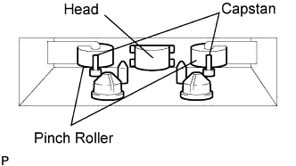

Using a cleaning pen or cotton applicator soaked in cleaner, clean the head surface, pinch rollers and capstans.
CD cleaning:
If a disc is dirty, clean the disc by wiping the CD's underside radially with a soft cloth.
- NOTICE:
- Do not use a conventional record cleaner or anti-static preservative.
| COMMUNICATION SYSTEM |
Components in the audio system communicate with each other through the Audio Visual Communication-Local Area Network (AVC-LAN).
The receiver has a resistance of 60 to 80 Ω, which is necessary for communication.
When a short circuit or circuit breakdown occurs in the AVC-LAN circuit, the audio system does not operate normally due to the communication cutoff.
| DIAGNOSIS FUNCTION |
The audio system has a diagnosis function. The diagnosis result is displayed on the LCD of the radio receiver.
A physical address (component code) is set for each component of the AVC-LAN.
A logical address is set for each function and component unit in each component of the AVC-LAN.
| DIAGNOSTIC TROUBLE CHART |
| Terms |
Definitions |
| Physical address (component code) |
|
| Logical address |
Two-digit code (in hexadecimals) given to each function and component unit in each component of AVC-LAN. |
- HINT:
- Titles for each unit below are stated in the following order: physical address (part name).
190 (RADIO RECEIVER)
Logical address: 01 (communication control) DTC
Diagnostic Item
Diagnostic Content
Troubleshooting
D6 *1
Absence of Master Component
With ignition switch on (ACC or IG), code related component disconnected from system or master component.
- Check harness of power supply system of radio receiver.
- Check harness of communication system of radio receiver.
D8 *2
No Response to Connection Check
Component shown by sub code disconnected from system after engine start.
- Check harness of power supply system of component shown by sub code.
- Check harness of communication system of component shown by sub code.
D9 *1
Last Mode Error
With ignition switch on (ACC or IG), audio or visual component operated before engine stop disconnected.
- Check harness of power supply system of component shown by sub code.
- Check harness of communication system of component shown by sub code.
DA
No Response to ON/OFF Instruction
No response when mode changed (audio and visual mode change). Sound and picture do not change by button operation.
- Check harness of power supply system of component shown by sub code.
- Check harness of communication system of component shown by sub code.
- If error occurs again, replace component shown by sub code.
DB *1
Mode Status Error
Dual alarm detected.
- Check harness of power supply system of component shown by sub code.
- Check harness of communication system of component shown by sub code.
DC *3
Transmission Error
Transmission failure to component shown by sub code. (Detecting this DTC does not necessarily mean actual failure.)
If same sub code is recorded in another component, check harness of power supply and communication systems of all components shown by code. If not, delete DTCs and recheck.
DD *4
Master Reset (Momentary Interruption)
Master component disconnected from system after engine start.
- Check harness of power supply system of radio receiver.
- Check harness of communication system of radio receiver.
- If this error occurs frequently, replace radio receiver.
DE *4
Slave Reset (Momentary Interruption)
Component shown by sub code disconnected from system after engine start.
- Check harness of power supply system of component shown by sub code.
- Check harness of communication system of component shown by sub code.
E0
Registration Completion Instruction Error
Registration Completion Instruction command from master component cannot be received.
Since this DTC is provided for engineering purposes, it may be detected when no actual failure exists.
E2
ON / OFF Instruction Parameter Request Transmission
Error occurs in ON / OFF controlling command from radio receiver.
Replace radio receiver.
E3
Registration Request Transmission
Registration Request command output from slave component.
Since this DTC is provided for engineering purposes, it may be detected when no actual failure exists.
E4
Plural Frame Abort
Plural frame transmission aborted.
Since this DTC is provided for engineering purposes, it may be detected when no actual failure exists.
- HINT:
- *1: May be recorded due to the battery condition or engine start voltage even if no failure is detected.
- *2: If the power connector is disconnected after the engine starts, this code is recorded after 180 seconds.
- *3: May be stored if the ignition switch is turned to START again while the engine is running.
- *4: May be stored if the ignition switch is held in START for one minute or more before returning it to ON.
Logical address: 61 (cassette switch) DTC
Diagnosis item
Diagnosis Content
Troubleshooting
40
Mechanical or Media Error
Malfunction due to mechanical failure identified, or cassette tape cut or entangled.
- Inspect cassette tape.
- Replace radio receiver.
Logical address: 62 (CD player) DTC
Diagnosis item
Diagnosis Content
Troubleshooting
42
No Disc Readout
Disc cannot be read.
- Inspect CD.
- Replace radio receiver.
44
CD Player Error
Error detected in CD player.
- Inspect CD.
- Replace radio receiver.
45
EJECT Error
Disc cannot be ejected.
Replace radio receiver.
46
Scratched / Reversed Disc
Scratches or dirt found on CD surface or CD set upside down.
Inspect CD.
47
Detection of High Temperature
High temperature detected in CD player.
Put vehicle in shade and allow it to cool down with ignition switch off, and then recheck for DTCs. If same DTC is detected, replace radio receiver.
48
Detection of Excess Current
Overcurrent detected in CD player.
Replace radio receiver.
Logical address: 63 (in-dash CD changer) DTC
Diagnosis item
Diagnosis Content
Troubleshooting
42
No Disc Readout
Disc cannot be read.
- Inspect CD.
- Replace radio receive.
44
CD Player Error
Error detected in CD player.
- Inspect CD.
- Replace radio receiver.
45
EJECT Error
Magazine cannot be ejected.
Replace radio receiver.
46
Scratched / Reversed Disc
Scratches or dirt found on CD surface or CD set upside down.
Inspect CD.
47
Detection of High Temperature
High temperature detected in CD changer.
Put vehicle in shade and allow it to cool down with ignition switch off, and then recheck for DTCs.
48
Detection of Excess Current
Overcurrent detected in CD changer.
Replace radio receiver.
51
CD Changer Elevator Error
Mechanical error occurs during elevator operation.
Replace radio receiver.
52
CD Changer Clamp Error
Failure in disc clamping or clamp error.
Replace radio receiver.
- Check harness of power supply system of radio receiver.