IG Power Source Circuit
Circuit diagnosis · Vehicles built from Aug 2005
DESCRIPTION
This is the main power source supplied to the air conditioning amplifier when the ignition switch is turned on (IG). This power source is used for operating components such as the air conditioning amplifier.WIRING DIAGRAM
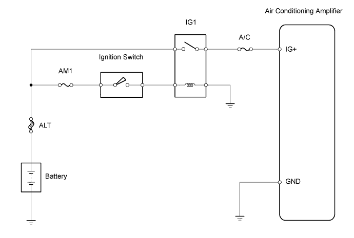

INSPECTION PROCEDURE
- HINT:
- Start the engine before the inspection. Check the IG1 relay or battery if the engine does not start.
| 1. INSPECT FUSE (A/C) |

Remove the A/C fuse from the main body ECU.
Measure the resistance.
- Standard resistance:
- Below 1 Ω
Reinstall the A/C fuse.
|
|
||||

| OK | |
 |
| 2. INSPECT AIR CONDITIONING AMPLIFIER |
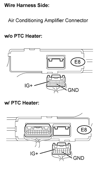 |
Disconnect the E8 air conditioning amplifier connector.
Measure the voltage.
- Standard voltage:
Tester Connection
Condition
Specified Condition
E8-8 (IG+) - E8-12 (GND)
Ignition switch on (IG)
10 to 14 V
Reconnect the air conditioning amplifier connector.
|
|
||||

| OK | ||
 |
||
| ||
| 3. CHECK HARNESS AND CONNECTOR (AIR CONDITIONING AMPLIFIER - MAIN BODY ECU) |
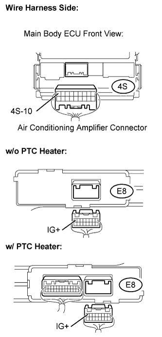 |
Disconnect the E8 air conditioning amplifier connector.
Disconnect the 4S main body ECU connector.
Measure the resistance.
- Standard resistance:
Tester Connection
Specified Condition
E8-8 (IG+) - 4S-10
Bellow 1 Ω
Reconnect the air conditioning amplifier connector.
Reconnect the main body ECU connector.
|
|
||||
| OK | |
|
| 4. CHECK HARNESS AND CONNECTOR (AIR CONDITIONING AMPLIFIER - BODY GROUND) |
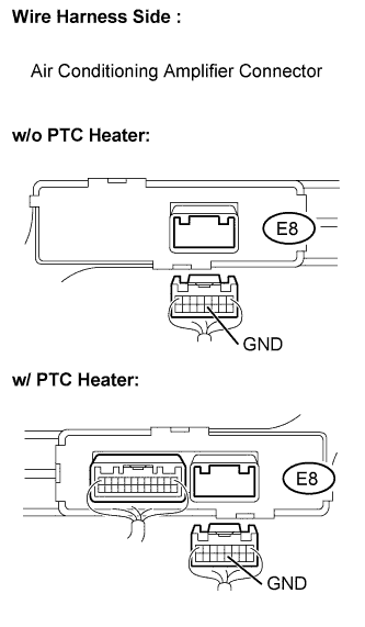 |
Disconnect the E8 air conditioning amplifier connector.
Measure the resistance.
- Standard resistance:
Tester Connection
Specified Condition
E8-12 (GND) - Body ground
Bellow 1 Ω
Reconnect the air conditioning amplifier connector.
|
|
||||
| OK | ||
|
||
| ||