INSTALLATION
Removal / installation · Vehicles built from Nov 2005
| 1. INSTALL INTERCOOLER ASSEMBLY |

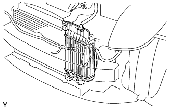  |
Install the 2 grommets.
Install the radiator support cushion.
Install the intercooler.
Connect the hose.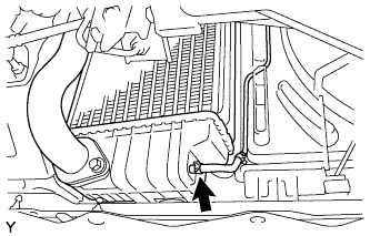
Engage the 2 clamps, and connect the wire harness.
| 2. INSTALL RADIATOR SUPPORT UPPER |
Install the radiator support upper with the 4 bolts.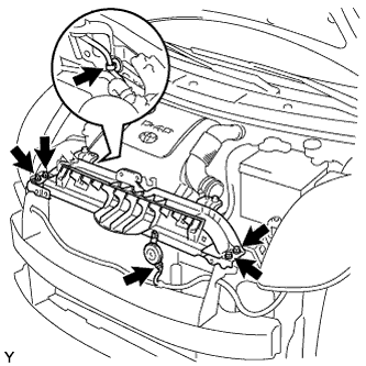
- Torque:
- 5.5 N*m{ 56 kgf*cm , 49 in.*lbf }
Engage the clamp, and connect the wire harness.
Connect the horn connector.
| 3. INSTALL RADIATOR RESERVE TANK ASSEMBLY |
Install the radiator reserve tank with the bolt.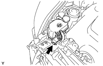
- Torque:
- 20 N*m{ 199 kgf*cm , 14 ft.*lbf }
| 4. INSTALL HOOD LOCK ASSEMBLY |
Provisionally tighten the 3 bolts.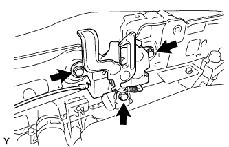
Connect the hood lock control cable to the radiator support upper.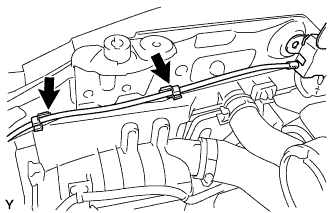
| 5. CONNECT AIR HOSE NO. 2 |
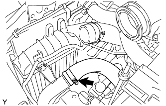 |
Connect air hose No. 2 with the hose clamp.
- Torque:
- 6.0 N*m{ 61 kgf*cm , 53 in.*lbf }
| 6. CONNECT AIR HOSE NO. 3 |
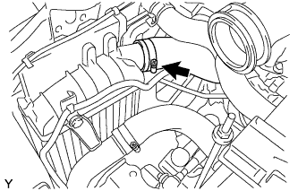 |
Connect air hose No. 3 with the hose clamp.
- Torque:
- 6.0 N*m{ 61 kgf*cm , 53 in.*lbf }
| 7. INSTALL AIR CLEANER ASSEMBLY |
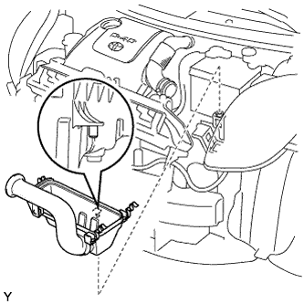 |
Align the protruding portion of the air cleaner case with the hole, as shown in the illustration, to install the air cleaner case onto the vehicle.
Tighten the air cleaner case with the 3 bolts.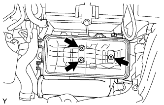
- Torque:
- 7.8 N*m{ 80 kgf*cm , 69 in.*lbf }
Install the air cleaner element.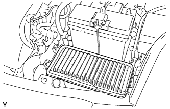
Connect the air cleaner hose with hose clamp to the air cleaner cap.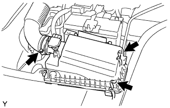
- Torque:
- 6.0 N*m{ 61 kgf*cm , 53 in.*lbf }
Install the air cleaner cap onto the air cleaner case, then hang the 2 hook clamps.
Fit the wire harness into the air cleaner cap.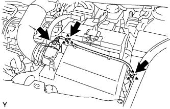
Connect the mass air flow meter connector.
| 8. INSTALL ENGINE UNDER COVER |
Provisionally install the engine under cover with the 5 bolts, 4 screws and 2 clips.
Tighten the 4 screws.
Tighten the 5 bolts.
- Torque:
- 5.0 N*m{ 51 kgf*cm , 44 in.*lbf }
| 9. INSTALL FRONT BUMPER COVER |
w/ Front Spoiler: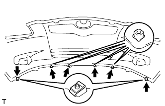
Install the 2 clips and the 4 screw grommets.
w/o Front Spoiler: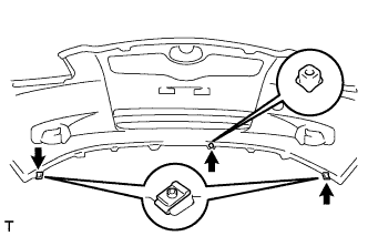
Install the 2 clips and the screw grommet.
w/ Fog Light:
Connect the 2 fog light connectors.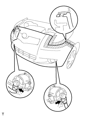
Engage the 6 claws and install the front bumper cover.
w/o Fog Light: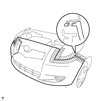
Engage the 6 claws and install the front bumper cover.
w/ Front Spoiler: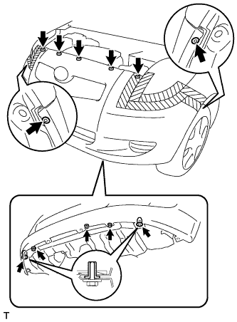
Install the 7 clips.
Install the 2 screw grommets.
Tighten the 3 screws.
w/o Front Spoiler: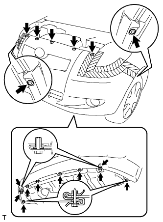
Install the 7 clips.
Install the 2 screw grommets.
Tighten the 8 screws.
Remove the protective tape.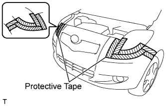
| 10. INSTALL FRONT SPOILER COVER RH (w/ Front Spoiler) |
Install the front spoiler cover with the 4 screws.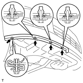
| 11. INSTALL FRONT SPOILER COVER LH (w/ Front Spoiler) |
Install the front spoiler cover with the 5 screws.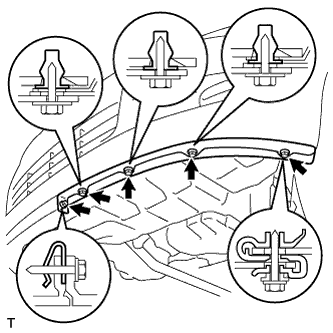
| 12. CONNECT CABLE TO NEGATIVE BATTERY TERMINAL |
- Torque:
- 5.4 N*m{ 55 kgf*cm , 48 in.*lbf }
| 13. INSPECT HOOD SUB-ASSEMBLY |
Check that the clearance measurements are within the standard ranges.
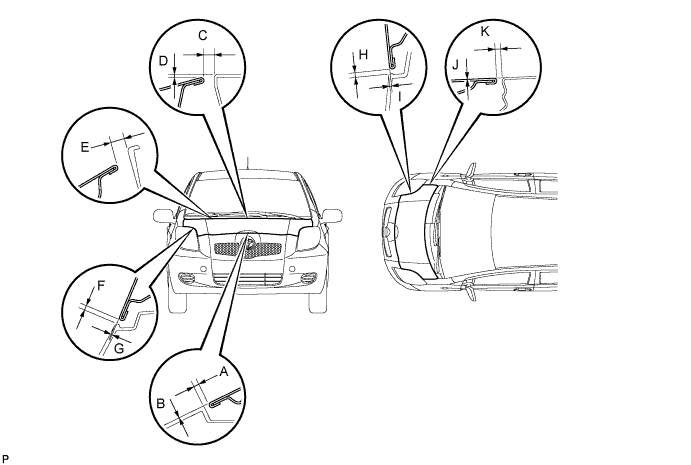
- Standard:
Area
Measurement
Area
Measurement
A
1.7 to 5.7 mm
(0.067 to 0.224 in.)
G
-1.55 to 2.45 mm
(-0.061 to 0.096 in.)
B
-2 to 2 mm
(-0.079 to 0.079 in.)
H
1.75 to 5.75 mm
(0.067 to 0.226 in.)
C
4.45 to 10.45 mm
(0.175 to 0.411 in.)
I
-1.25 to 2.75 mm
(-0.049 to 0.108 in.)
D
-0.95 to 5.05 mm
(-0.037 to 0.199 in.)
J
-1.5 to 1.5 mm
(-0.059 to 0.059 in.)
E
7.55 to 13.55 mm
(0.297 to 0.533 in.)
K
2.0 to 5.0 mm
(0.079 to 0.197 in.)
F
1.65 to 5.65 mm
(0.065 to 0.222 in.)
-
-
| 14. ADJUST HOOD SUB-ASSY |
Loosen the hood side hinge bolts.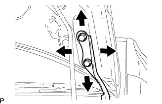
Move the hood to adjust the clearance to within the standard range.
Tighten the hood side hinge bolts after the adjustment.
- Torque:
- 13 N*m{ 133 kgf*cm , 10 ft.*lbf }
Adjust the height of the hood front end by turning the cushion rubber.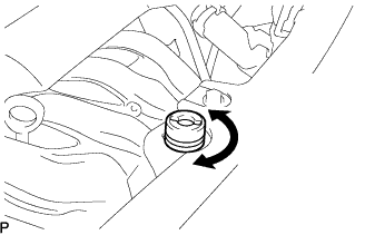
- HINT:
- The cushion rubber can be raised and lowered by turning it.
Adjust the hood lock.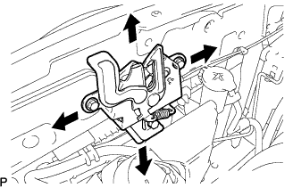
Loosen the 3 bolts.
Adjust the hood lock position so that the striker can enter it smoothly.
Tighten the 3 bolts after the adjustment.
- Torque:
- 7.5 N*m{ 76 kgf*cm , 66 in.*lbf }