INSTALLATION
Removal / installation · Vehicles built from Nov 2005
| 1. INSTALL TURBO OIL OUTLET PIPE |

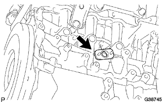  |
Install a new gasket onto the cylinder block.
Provisionally install the turbo oil outlet pipe with 2 new nuts.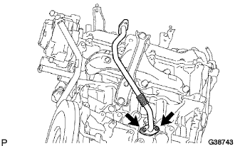
| 2. INSTALL TURBOCHARGER SUB-ASSEMBLY |
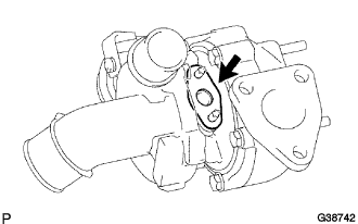 |
Install a new gasket onto the turbocharger.
Install a new gasket onto the exhaust manifold.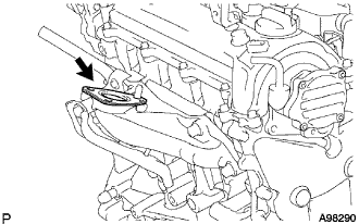
Install the turbocharger with the 3 nuts.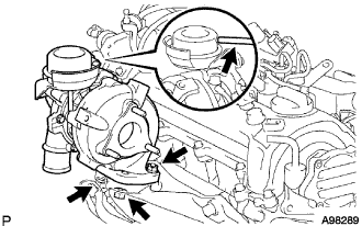
- Torque:
- 53 N*m{ 540 kgf*cm , 39 ft.*lbf }
Connect the vacuum hose to the turbocharger.
Tighten 2 new nuts B.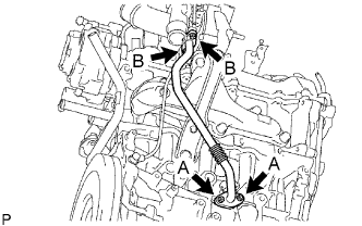
- Torque:
- 11 N*m{ 110 kgf*cm , 8 ft.*lbf }
Tighten 2 new nuts A.
- Torque:
- 14 N*m{ 140 kgf*cm , 10 ft.*lbf }
| 3. INSTALL AIR HOSE NO. 1 |
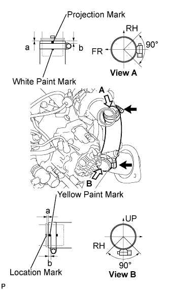 |
Install the intercooler air hose with the 2 hose clamps.
- Torque:
- 6.0 N*m{ 60 kgf*cm , 53 in.*lbf }
- Specification:
Area
Measurement
a
0 to 2 mm (0 to 0.079 in.)
b
2 to 5 mm (0.079 to 0.197 in.)
- NOTICE:
- Align the paint mark of the intercooler air hose with the location mark of the turbocharger.
- Align the paint mark of the intercooler air hose with the location mark of air tube No. 1.
- Make sure that the hose clamp is at the correct angle when installing.
- Align the paint mark of the intercooler air hose with the location mark of the turbocharger.
| 4. INSTALL TURBO OIL INLET PIPE |
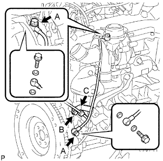 |
Install 4 new gaskets and the turbo oil inlet pipe with 2 union bolts A.
- Torque:
- 24 N*m{ 245 kgf*cm , 18 ft.*lbf }
Tighten bolt B.
- Torque:
- 11 N*m{ 110 kgf*cm , 8 ft.*lbf }
Install wire harness clamp C.
| 5. INSTALL EXHAUST MANIFOLD CONVERTER SUB-ASSEMBLY |
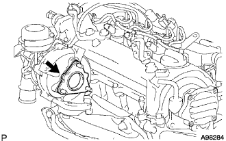 |
Install a new gasket onto the turbocharger.
Temporarily install the exhaust manifold converter with 3 new nuts A.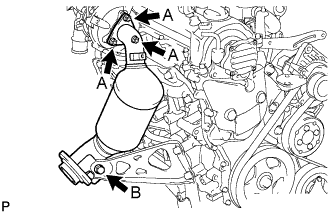
Provisionally install the manifold support bracket with the bolt B.
Tighten 3 nuts A.
- Torque:
- 26 N*m{ 265 kgf*cm , 19 ft.*lbf }
Tighten bolt B.
- Torque:
- 37 N*m{ 375 kgf*cm , 27 ft.*lbf }
| 6. INSTALL TURBO INSULATOR NO. 1 |
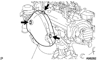 |
Install turbo insulator No. 1 with the 3 bolts.
- Torque:
- 6.0 N*m{ 60 kgf*cm , 53 in.*lbf }
For LHD: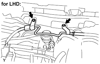
Install the 2 bolts and brake booster vacuum pipe.
- Torque:
- 8.3 N*m{ 85 kgf*cm , 73 in.*lbf }
For RHD: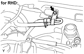
Install the bolt and brake booster vacuum pipe.
- Torque:
- 8.3 N*m{ 85 kgf*cm , 73 in.*lbf }
| 7. INSTALL EXHAUST PIPE ASSEMBLY FRONT |
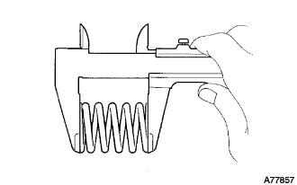 |
Check the free length.
Using vernier calipers, measure the free length of the compression spring.
- Minimum length:
- 40.5mm (1.594 in.)
Using a wooden block and plastic-hammer, tap in a new gasket until it is flush with the exhaust manifold converter.
- NOTICE:
- Make sure that the gasket is in the correct direction when installing it.
- Do not reuse a removed gasket.
- Never push the gasket into the exhaust manifold converter by installing the exhaust pipe front onto the exhaust manifold converter.
- Make sure that the gasket is in the correct direction when installing it.
Install the exhaust pipe front onto the 3 exhaust pipe supports.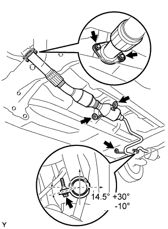
Install a new gasket onto the exhaust pipe front.
Install a new clamp with the bolt as shown in the illustration.
- Torque:
- 32 N*m{ 326 kgf*cm , 24 ft.*lbf }
- NOTICE:
- Do not reuse the removed gasket and clamp.
- Make sure that the pipe clamp is at the correct angle when installing it.
- Do not reuse the removed gasket and clamp.
Install the exhaust pipe front with the 2 compression springs and 2 bolts.
- Torque:
- 43 N*m{ 440 kgf*cm , 32 ft.*lbf }
| 8. INSTALL COWL TOP PANEL OUTER |
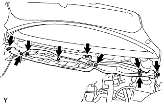 |
Install the cowl top panel outer with the 9 bolts.
- Torque:
- 6.5 N*m{ 66 kgf*cm , 58 in.*lbf }
Install the wire harness.
| 9. INSTALL COWL TO REGISTER DUCT SUB-ASSEMBLY NO. 2 |
| 10. INSTALL FRONT WIPER MOTOR AND LINK ASSEMBLY |
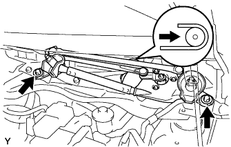 |
Connect the connector.
Slide the wiper link as shown in the illustration and engage the rubber pin with the body.
Install the front wiper motor and link with the 2 bolts.
- Torque:
- 5.5 N*m{ 56 kgf*cm , 49 in.*lbf }
| 11. INSTALL COWL TOP VENTILATOR LOUVER LH (for LHD) |
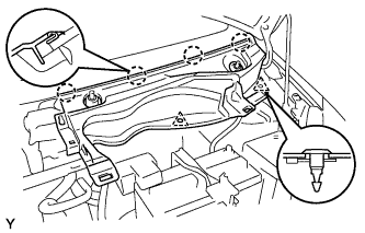 |
Engage the 4 claws and install the cowl top ventilator louver LH.
Install the 2 clips.
| 12. INSTALL COWL TOP VENTILATOR LOUVER SUB-ASSEMBLY (for LHD) |
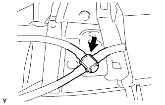 |
Connect the washer hose.
Engage the 11 claws and install the cowl top ventilator louver sub-assembly.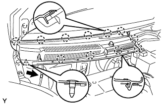
Install the clip.
Connect the washer hose.
Engage the 2 hooks and install cowl top ventilator louver center No. 1.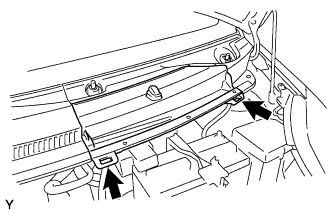
| 13. INSTALL COWL TOP VENTILATOR LOUVER LH (for RHD) |
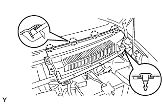 |
Engage the 4 claws and install the cowl top ventilator louver LH.
Install the clip.
| 14. INSTALL COWL TOP VENTILATOR LOUVER SUB-ASSEMBLY (for RHD) |
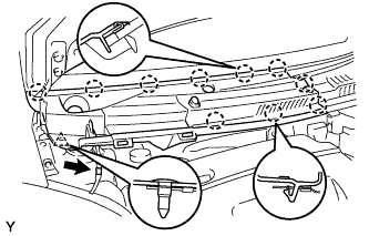 |
Engage the 10 claws and install the cowl top ventilator louver sub-assembly.
Install the clip.
Connect the washer hose.
| 15. INSTALL HOOD TO COWL TOP SEAL |
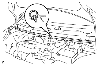 |
Engage the 7 clips and install the hood to cowl top seal.
| 16. INSTALL FRONT WIPER ARM AND BLADE SUB-ASSEMBLY LH |
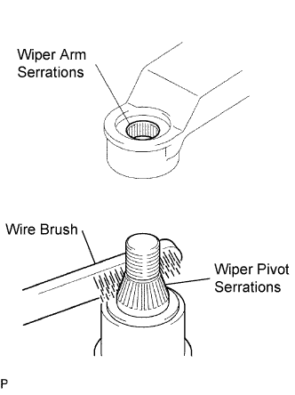 |
Scrape any metal powder off the serrated part of the wiper arm with a round file or the equivalent (when reinstalling).
Clean the wiper pivot serrations with a wire brush.
Operate the wiper, then stop the windshield wiper motor in the automatic stop position.
Align the blade tip with the mark on the windshield glass, as shown in the illustration.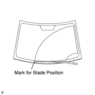
Tighten the nut of the front wiper arm.
- Torque:
- 26 N*m{ 265 kgf*cm , 19 ft.*lbf }
| 17. INSTALL FRONT WIPER ARM AND BLADE SUB-ASSEMBLY RH |
|
|
Scrape any metal powder off the serrated part of the wiper arm with a round file or the equivalent (when reinstalling).
Clean the wiper pivot serrations with a wire brush.
Operate the wiper, then stop the windshield wiper motor in the automatic stop position.
Align the blade tip with the mark on the windshield glass, as shown in the illustration.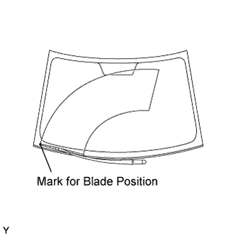
Tighten the nut of the front wiper arm.
- Torque:
- 26 N*m{ 265 kgf*cm , 19 ft.*lbf }
| 18. INSTALL FRONT WIPER ARM HEAD CAP |
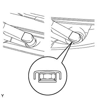 |
Engage the claw and install the 2 front wiper arm head caps.
| 19. INSTALL AIR CLEANER FILTER ELEMENT SUB-ASSEMBLY |
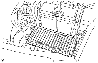 |
Install the air cleaner filter element onto the air cleaner case.
| 20. INSTALL AIR CLEANER CAP SUB-ASSEMBLY WITH HOSE |
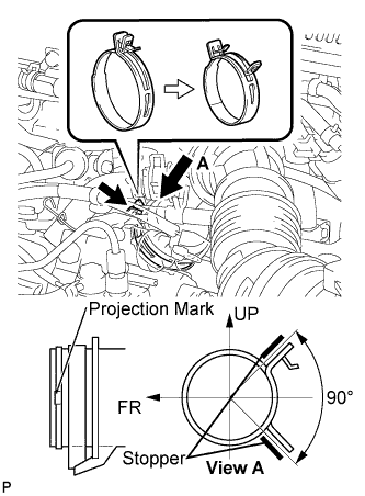 |
Align the matchmarks of air cleaner hose No. 1 and turbocharger, and connect air cleaner hose No. 1 to the turbocharger and fasten air cleaner hose clamp No. 1.
- NOTICE:
- Make sure that the hose clamp is at the correct angle when installing it.
Connect the ventilation hose to the cylinder head cover.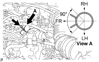
- NOTICE:
- Make sure that the hose clamp is at the correct angle when installing it.
Install the air cleaner cap onto the air cleaner case, then hang the 2 hook clamps.
Fit the wire harness into the air cleaner cap.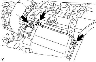
Engage the 2 wire harness clamps.
Connect the mass air flow meter connector.
| 21. CONNECT CABLE TO NEGATIVE BATTERY TERMINAL |
- Torque:
- 5.4 N*m{ 55 kgf*cm , 48 in.*lbf }
| 22. ADD ENGINE OIL |
| 23. CHECK FOR ENGINE OIL LEAKAGE |
| 24. CHECK FOR EXHAUST GAS LEAKAGE |
| 25. INSTALL ENGINE COVER SUB-ASSEMBLY NO. 1 |
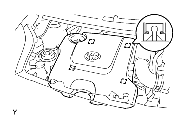 |
Engage the 4 pins and install engine cover No. 1.