Stop Light Circuit
Circuit diagnosis · Vehicles built Aug 2005 – Oct 2006
Versions by build date: Aug 2005 – Oct 2006 from Nov 2006
DESCRIPTION
When the stop light switch is turned on, the current flows to the stop lights to illuminate.WIRING DIAGRAM
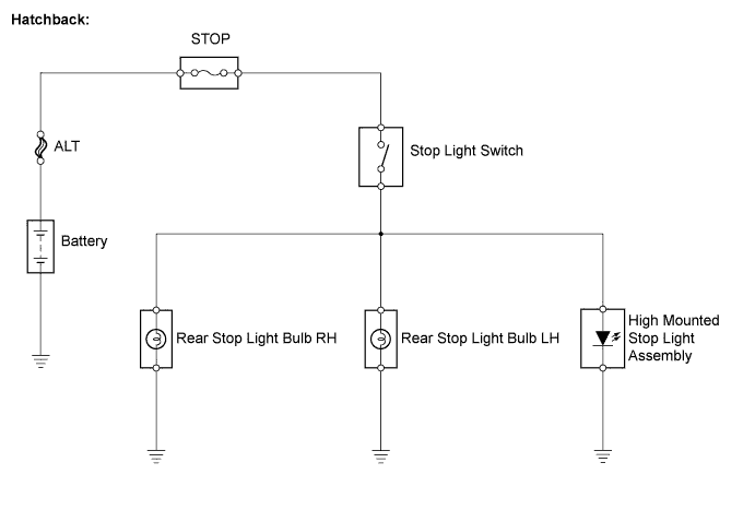

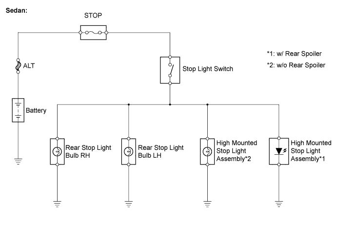
INSPECTION PROCEDURE
| 1. INSPECT FUSE (STOP) |

Remove the STOP fuse from the main body ECU.
Measure the resistance.
- Standard resistance:
- Below 1 Ω
Reinstall the STOP fuse.
|
|
||||

| OK | |
 |
| 2. INSPECT BULB (REAR STOP LIGHT BULB) |
Hatchback:
Remove the rear combination light assembly.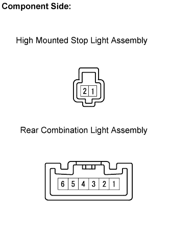
Remove the high mounted stop light assembly.
Apply battery voltage to the terminals and check that the rear stop light and high mounted stop light illuminate.
- Standard:
- Rear Stop Light:
Measurement Condition
Standard
Positive battery - Terminal 5
Negative battery - Terminal 6
Rear stop light illuminates
- High Mounted Stop Light:
Measurement Condition
Standard
Positive battery - Terminal 1
Negative battery - Terminal 2
High mounted stop light illuminates
Reinstall the rear combination light assembly.
Reinstall the high mounted stop light assembly.
Sedan:
Remove the rear combination light assembly.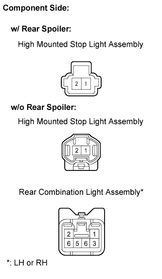
Remove the high mounted stop light assembly.
Apply battery voltage to the terminals and check that the rear stop light and high mounted stop light illuminate.
- Standard:
- Rear Stop Light:
Measurement Condition
Standard
Positive battery - Terminal 1
Negative battery - Terminal 6
Rear stop light illuminates
- High Mounted Stop Light (w/ Rear Spoiler):
Measurement Condition
Standard
Positive battery - Terminal 2
Negative battery - Terminal 1
High mounted stop light illuminates
- High Mounted Stop Light (w/o Rear Spoiler):
Measurement Condition
Standard
Positive battery - Terminal 1
Negative battery - Terminal 2
High mounted stop light illuminates
Reinstall the rear combination light assembly.
Reinstall the high mounted stop light assembly.
|
|
||||
| OK | |
|
| 3. INSPECT STOP LIGHT SWITCH |
Remove the stop light switch.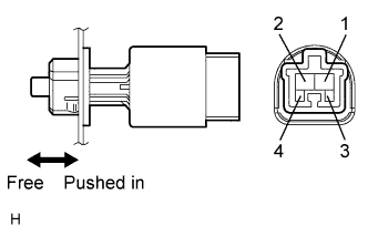
Measure the resistance.
- Standard resistance:
Tester Connection
Condition
Specified Condition
1 - 2
Switch pin released
Below 1 Ω
3 - 4
Switch pin pushed in
10 kΩ or higher
1 - 2
Switch pin pushed in
10 kΩ or higher
3 - 4
Switch pin released
Below 1 Ω
Reinstall the stop light switch.
|
|
||||
| OK | |
|
| 4. CHECK HARNESS AND CONNECTOR (STOP FUSE - STOP LIGHT SWITCH) |
Disconnect the A13 stop light switch connector.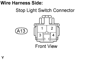
Measure the voltage.
- Standard voltage:
Tester Connection
Condition
Specified Condition
A13-2 - Body Ground
Always
10 to 14 V
Reconnect the stop light switch connector.
|
|
||||
| OK | |
|
| 5. CHECK HARNESS AND CONNECTOR (STOP LIGHT SWITCH - REAR STOP LIGHT) |
Hatchback:
Disconnect the A13 stop light switch connector.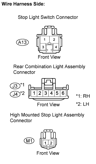
Disconnect the J3 and J4 rear combination light assembly connectors.
Disconnect the M1 high mounted stop light assembly connector.
Measure the resistance.
- Standard resistance:
Tester Connection
Specified Condition
A13-1 - J3-5
Below 1 Ω
A13-1 - J4-5
Below 1 Ω
A13-1 - M1-1
Below 1 Ω
A13-1 or J3-5 - Body ground
10 kΩ or higher
A13-1 or J4-5 - Body ground
10 kΩ or higher
A13-1 or M1-1 - Body ground
10 kΩ or higher
Reconnect the stop light switch connector.
Reconnect the rear combination light assembly connectors.
Reconnect the high mounted stop light assembly connector.
Sedan: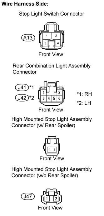
Disconnect the A13 stop light switch connector.
Disconnect the J41 and J42 rear combination light assembly connectors.
Disconnect the J47 high mounted stop light assembly connector (Without rear spoiler).
Remove the high mounted stop light assembly (With rear spoiler).
Measure the resistance.
- Standard resistance:
Tester Connection
Specified Condition
A13-1 - J41-1
Below 1 Ω
A13-1 - J42-1
Below 1 Ω
A13-1 - High mounted stop light assembly-2*1
Below 1 Ω
A13-1 - J47-1*2
Below 1 Ω
A13-1 or J41-1 - Body ground
10 kΩ or higher
A13-1 or J42-1 - Body ground
10 kΩ or higher
A13-1 or High mounted stop light assembly-2*1 - Body ground
10 kΩ or higher
A13-1 or J47-1*2 - Body ground
10 kΩ or higher
- HINT:
- *1: w/ Rear spoiler
- *2: w/o Rear spoiler
Reconnect the stop light switch connector.
Reconnect the rear combination light assembly connectors.
Reconnect the high mounted stop light assembly connector (without rear spoiler).
Reinstall the high mounted stop light assembly (with rear spoiler).
|
|
||||
| OK | ||
 |
||
| ||