DRL Relay Circuit
Circuit diagnosis · Vehicles built from Aug 2005
DESCRIPTION
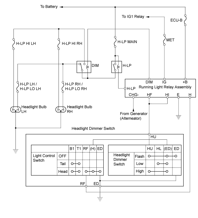
When the engine is started, signals are transmitted from the generator to the running light relay assembly. The running light relay assembly illuminates the headlights when it receives the signals.WIRING DIAGRAM

INSPECTION PROCEDURE
| 1. CHECK WHETHER HEADLIGHTS ILLUMINATE |

Check whether the headlights illuminate.
- Result:
Condition
proceed to
Either left or right headlight does not illuminate
A
Neither headlight illuminates
B
|
|
||||

| A | |
 |
| 2. INSPECT BULB (HEADLIGHT BULB) |
Disconnect the B4 and B6 headlight connectors.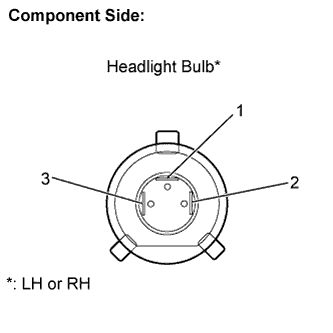
Apply battery voltage to the terminals and check that the headlight illuminates.
- Standard:
Measurement Condition
Standard
Positive battery - Terminal 1
Negative battery - Terminal 3
Headlight illuminates (HI-Beam)
Positive battery - Terminal 2
Negative battery - Terminal 3
Headlight illuminates (LO-Beam)
Reconnect the headlight connectors.
|
|
||||

| OK | |
|
| 3. INSPECT FUSE (H-LP LH/H-LP LO LH, H-LP RH/H-LP LO RH, H-LP HI LH, H-LP RH) |
Remove the H-LP LH/H-LP LO LH and H-LP RH/H-LP LO RH fuses from the engine room relay block.
Remove the H-LP HI LH and H-LP HI RH fuses from the engine room relay block No. 7
Measure the resistance.
- Standard resistance:
- Below 1 Ω
Reinstall the H-LP LH/H-LP LO LH , H-LP RH/H-LP LO RH, H-LP HI LH and H-LP HI RH fuses.
|
|
||||
| OK | |
|
| 4. CHECK HARNESS AND CONNECTOR (DIM RELAY - HEADLIGHT BULB) |
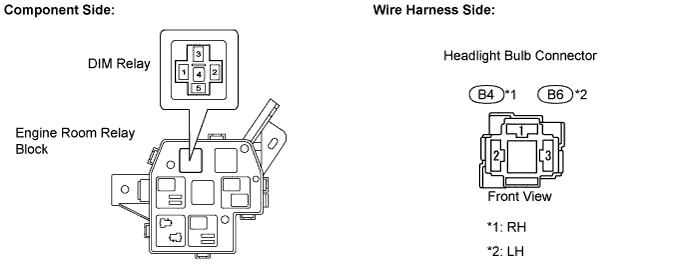
Disconnect the B4 and B6 headlight bulb connectors.
Remove the DIM relay from the engine room relay block.
Measure the resistance.
- Standard resistance:
Tester connection
Specified Condition
DIM relay terminal 4 - B4-1
Below 1 Ω
DIM relay terminal 4 or B4-1 - Body ground
10 kΩ or higher
DIM relay terminal 5 - B4-2
Below 1 Ω
DIM relay terminal 5 or B4-2 - Body ground
10 kΩ or higher
DIM relay terminal 4 - B6-1
Below 1 Ω
DIM relay terminal 4 or B6-1 - Body ground
10 kΩ or higher
DIM relay terminal 5 - B6-2
Below 1 Ω
DIM relay terminal 5 or B6-2 - Body ground
10 kΩ or higher
Reconnect the headlight bulb connectors.
Reinstall the DIM relay.
|
|
||||
| OK | ||
 |
||
| ||
| 5. INSPECT FUSE (H-LP MAIN, ECU-B, MET) |
Remove the H-LP MAIN and ECU-B fuses from engine room relay block.
Remove the MET fuse from main body ECU.
Measure the resistance.
- Standard resistance:
- Below 1 Ω
Reinstall the H-LP MAIN, ECU-B and MET fuses.
|
|
||||
| OK | |
|
| 6. INSPECT H-LP RELAY |
Remove the H-LP relay.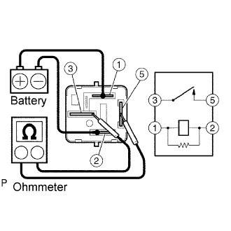
Measure the resistance.
- Standard resistance:
Tester connection
Specified Condition
3 - 5
10 kΩ or higher
3 - 5
Below 1 Ω
(Battery voltage applied to terminals 1 and 2)
Reinstall the H-LP relay.
|
|
||||
| OK | |
|
| 7. INSPECT DIM RELAY |
Remove the DIM relay.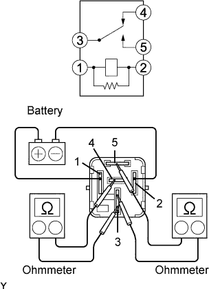
Measure the resistance.
- Standard resistance:
Tester connection
Specified Condition
3 - 4
Below 1 Ω
3 - 4
10 kΩ or higher
(Battery voltage applied to terminals 1 and 2)
3 - 5
10 kΩ or higher
3 - 5
Below 1 Ω
(Battery voltage applied to terminals 1 and 2)
Reinstall the DIM relay.
|
|
||||
| OK | |
|
| 8. CHECK HARNESS AND CONNECTOR (FUSE - H-LP RELAY) |
Remove the H-LP relay.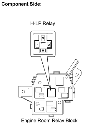
Measure the voltage.
- Standard voltage:
Tester connection
Condition
Specified Condition
H-LP relay terminal 1 - Body round
Always
10 to 14 V
H-LP relay terminal 5 - Body round
Always
10 to 14 V
Reinstall the H-LP relay.
|
|
||||
| OK | |
|
| 9. CHECK HARNESS AND CONNECTOR (H-LP RELAY - DIM RELAY) |
Remove the H-LP relay from the engine room relay block.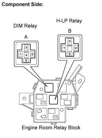
Remove the DIM relay from the engine room relay block.
Measure the resistance.
- Standard resistance:
Tester connection
Specified Condition
B-3 - A-2
Below 1 Ω
B-3 or A-2 - Body ground
10 kΩ or higher
B-3 - A-3
Below 1 Ω
B-3 or A-3 - Body ground
10 kΩ or higher
Reinstall the H-LP relay.
Reinstall the DIM relay.
|
|
||||
| OK | |
|
| 10. CHECK HARNESS AND CONNECTOR (DIM RELAY - RUNNING LIGHT RELAY ASSEMBLY) |
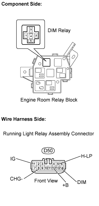 |
Disconnect the D50 running light relay assembly connector.
Measure the voltage.
- Standard voltage:
Tester connection
Condition
Specified Condition
D50-1 (IG) - Body ground
Ignition Switch on (IG)
10 to 14 V
D50-5 (H-LP) - Body ground
Always
10 to 14 V
D50-8 (CHG-) - Body ground
Vehicle stopped and engine idling
10 to 14 V
D50-12 (+B) - Body ground
Always
10 to 14 V
Remove the DIM relay.
Measure the resistance.
- Standard resistance:
Tester Connection
Specified Condition
DIM relay terminal 1 - D50-14 (DIM)
Below 1 Ω
DIM relay terminal 1 or D50-14 (DIM) - Body ground
10 kΩ or higher
Reconnect the running light relay assembly connector.
Reinstall the DIM relay.
|
|
||||
| OK | |
|
| 11. INSPECT HEADLIGHT DIMMER SWITCH |
Remove the headlight dimmer switch.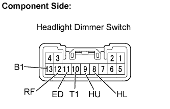
Inspect the light control switch.
Measure the resistance.
- Standard resistance:
Tester connection
Condition
Specified Condition
10 (T1) - 13 (B1)
TAIL
Below 1 Ω
10 (T1) - 13 (B1)
OFF
10 kΩ or higher
10 (T1) - 13 (B1)
HEAD
Below 1 Ω
10 (T1) - 13 (B1)
OFF
10 kΩ or higher
11 (ED) - 12 (RF)
HEAD
Below 1 Ω
11 (ED) - 12 (RF)
OFF
10 kΩ or higher
Inspect the headlight dimmer switch.
Measure the resistance.
- Standard resistance:
Tester connection
Condition
Specified Condition
9 (HU) - 11 (ED)
FLASH
Below 1 Ω
8 (HL) - 11 (ED)
LOW BEAM
Below 1 Ω
9 (HU) - 11 (ED)
HI BEAM
Below 1 Ω
Reinstall the headlight dimmer switch.
|
|
||||
| OK | |
|
| 12. CHECK HARNESS AND CONNECTOR (HEADLIGHT DIMMER SWITCH - RUNNING LIGHT RELAY ASSEMBLY) |
Disconnect the D50 running light relay assembly connector.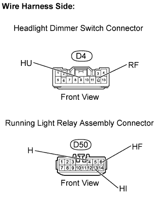
Disconnect the D4 headlight dimmer switch connector.
Measure the resistance.
- Standard resistance:
Tester connection
Specified Condition
D4-9 (HU) - D50-6 (HF)
Below 1 Ω
D4-9 (HU) - D50-13 (HI)
Below 1 Ω
D4-12 (RF) - D50-4 (H)
Below 1 Ω
D4-9 (HU) or D50-6 (HF) - Body ground
10 kΩ or higher
D4-9 (HU) or D50-13 (HI) - Body ground
10 kΩ or higher
D4-12 (RF) or D50-4 (H) - Body ground
10 kΩ or higher
Reconnect the running light relay assembly connector.
Reconnect the headlight dimmer switch connector.
|
|
||||
| OK | |
|
| 13. CHECK HARNESS AND CONNECTOR (RUNNING LIGHT RELAY ASSEMBLY - BODY GROUND) |
Disconnect the D50 running light relay assembly connector.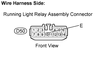
Measure the resistance.
- Standard resistance:
Tester connection
Specified Condition
D50-10 (E) - Body ground
Below 1 Ω
Reconnect the running light relay assembly connector.
|
|
||||
| OK | ||
|
||
| ||