REMOVAL
Removal / installation · Vehicles built from Nov 2005
| 1. DISCONNECT CABLE FROM NEGATIVE BATTERY TERMINAL |
| 2. DRAIN ENGINE COOLANT |

- CAUTION:
- To avoid the danger of being burned, do not remove the radiator cap while the engine and radiator are still hot. Thermal expansion will cause hot engine coolant and steam to blow out from the radiator.
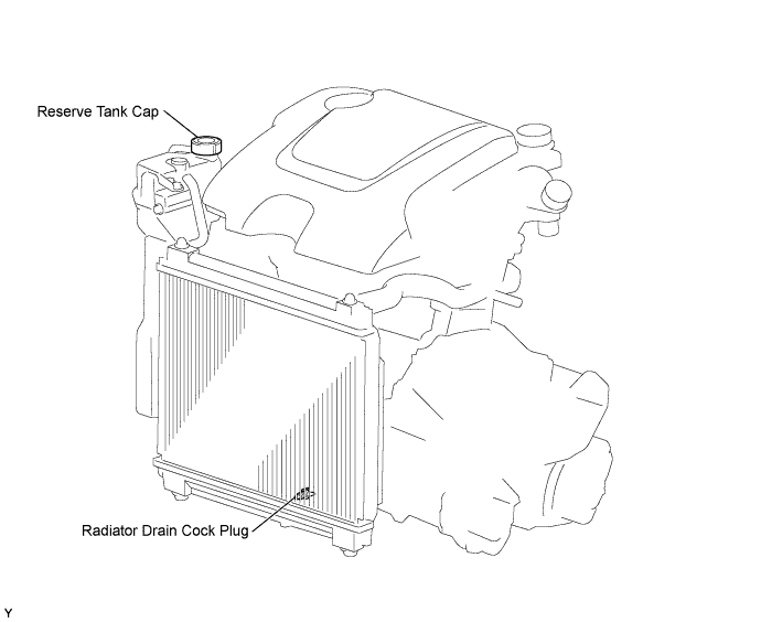
Loosen the radiator drain cock plug.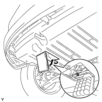

Remove the reserve tank cap and drain the coolant.
Tighten the radiator drain cock plug.
| 3. REMOVE FRONT WHEEL RH |
| 4. REMOVE ENGINE UNDER COVER |
Remove the 5 bolts, 4 screws and 2 clips and remove the engine under cover.
| 5. REMOVE ENGINE COVER SUB-ASSEMBLY NO. 1 |
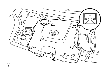 |
Disengage the 4 pins and remove engine cover No. 1.
| 6. REMOVE CYLINDER HEAD COVER SUB-ASSEMBLY |
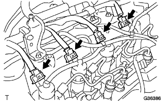 |
Disconnect the injector connectors.
Disconnect the supply pump connector.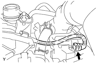
Disengage the wire harness clamps shown in the illustration.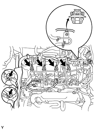
Disconnect the VSV connector shown in the illustration, and disengage the wire harness clamp shown in the illustration.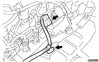
Remove the screw grommet and nut, then separate the wire harness.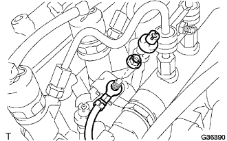
Disconnect the common rail connector.
Remove the 3 bolts and the wire harness clamp shown in the illustration and disconnect the engine wire harness.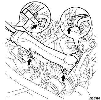
Disconnect the hose shown in the illustration.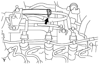
Disconnect the hose shown in the illustration.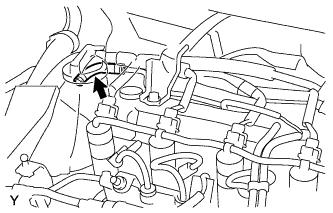
Disconnect the 3 vacuum hoses shown in the illustration.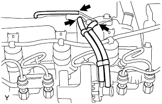
Disconnect the vacuum hose shown in the illustration.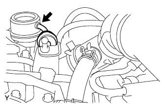
Disconnect the ventilation hose from the cylinder head.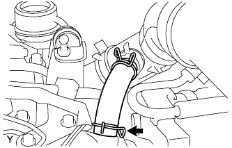
Remove the 2 bolts, then remove the connector to vacuum reservoir tube.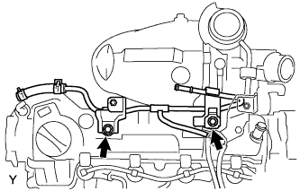
Remove the 12 bolts, then remove the cylinder head cover.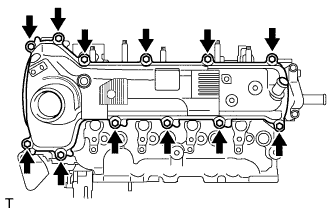
| 7. REMOVE VACUUM PUMP ASSEMBLY |
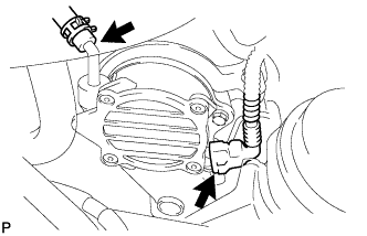 |
Slide the clip and disconnect the vacuum hose.
Disconnect the cam position sensor connector.
Remove the 2 bolts and vacuum pump.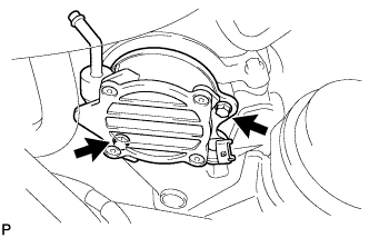
Remove the 2 O-rings from the vacuum pump.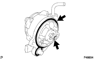
| 8. REMOVE AIR CLEANER CAP SUB-ASSEMBLY WITH HOSE |
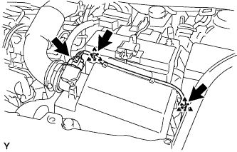 |
Disconnect the mass air flow meter connector.
Disengage the 2 wire harness clamps, and separate the wire harness from the air cleaner cap.
Unfasten the 2 lock clamps, and separate the air cleaner cap.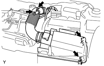
Disconnect the ventilation hose from the cylinder head cover.
Disconnect the air cleaner hose from the turbocharger, and remove the air cleaner with hose.
| 9. REMOVE EGR COOLER ASSEMBLY |
Disconnect the 2 water by-pass hoses.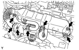
Remove the bolt and 4 nuts, then remove the EGR cooler assembly.
Remove the 2 gaskets.
| 10. REMOVE VACUUM REGULATING VALVE ASSEMBLY |
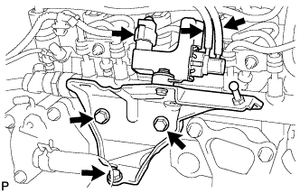 |
Disconnect the connector clamp and connector.
Disengage the 2 hose clamps and disconnect the 2 vacuum hoses.
Remove the 3 bolts, then remove the vacuum regulating valve together with the bracket.
| 11. REMOVE INJECTION PIPE CLAMP NO. 1 |
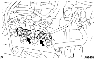 |
Remove the 2 nuts, then remove injection pipe clamp No. 1.
| 12. REMOVE NOZZLE LEAKAGE PIPE ASSEMBLY |
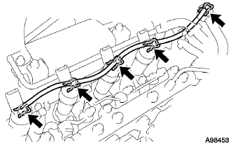 |
Remove the 5 retainer springs, then remove the nozzle leakage pipe.
| 13. REMOVE FUEL INLET PIPE SUB-ASSEMBLY |
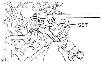 |
Using a spanner (17 mm), hold the supply pump steady, and using SST, remove the fuel inlet pipe from the supply pump side.
- SST
- 09023-38401
Using SST, remove the fuel inlet pipe from the common rail side.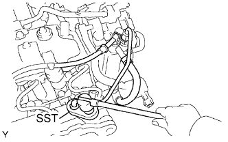
- SST
- 09023-38401
After removing the fuel inlet pipe, cover the common rail with vinyl tape and cover the injector inlet with a vinyl or plastic bag in order to prevent dust and foreign matter from entering.
| 14. REMOVE INJECTION OR SUPPLY PUMP ASSEMBLY |
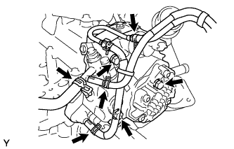 |
Disconnect the 3 fuel hoses.
Disconnect the 2 connectors.
Remove the 3 bolts, then remove the supply pump.
Remove the supply pump driving coupling.
Remove the O-ring.
- NOTICE:
- When removing the supply pump, make sure that the drive coupling does not fall off, as it can be easily removed. If the drive coupling falls off, replace it with a new one.
| 15. REMOVE CAMSHAFT |
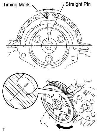 |
Set the No. 1 cylinder to TDC/Compression.
Turn the crankshaft pulley until the grooves of the crankshaft damper and oil pump are aligned.
Check that the timing mark of the camshaft timing sprocket and the straight pin hole in the camshaft timing sprocket are in the positions shown in the illustration.
- HINT:
- If not, turn the crankshaft damper 1 revolution (360°) to align them as above.
Put paint marks on the timing chain plates which align with the timing marks of the camshaft timing sprocket.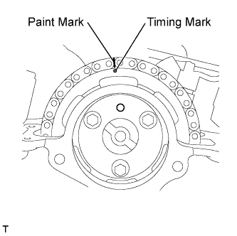
Using an 8 mm socket hexagon wrench, remove the service hole screw plug.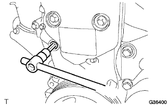
Insert a flat head screwdriver from the chain tensioner service hole and hold the chain tensioner stopper plate in a raised position.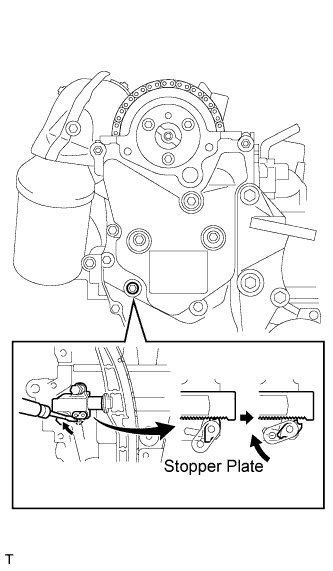
Use a wrench to turn the hexagon service portion of the camshaft and keep the chain tensioner plunger depressed.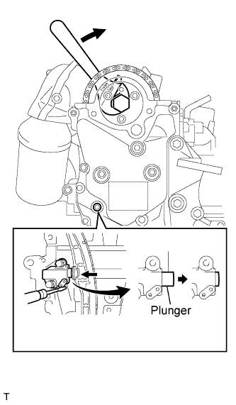
Remove the flat head screwdriver from the chain tensioner service hole. Insert a 2.5 mm (0.098 in.) diameter bar into the hole in the stopper plate with the stopper plate lowered.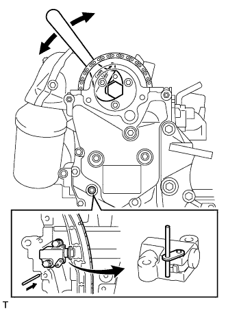
- HINT:
- The stopper plate can be easily pulled down and an hexagon key wrench can be easily inserted by turning the camshaft counterclockwise slightly and then turning it clockwise.
- Secure the 2.5 mm (0.098 in.) diameter bar using tape or the equivalent to keep it from falling off.
- The stopper plate can be easily pulled down and an hexagon key wrench can be easily inserted by turning the camshaft counterclockwise slightly and then turning it clockwise.
While holding the hexagonal service portion of the camshaft with a wrench, loosen the 3 bolts.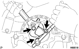
Remove the 10 bolts of the camshaft bearing caps in the sequence shown in the illustration, and then remove the 5 camshaft bearing caps.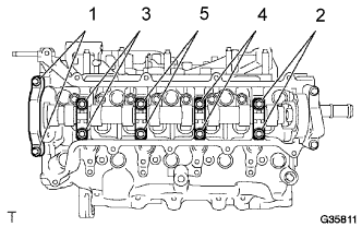
- NOTICE:
- Using several steps, uniformly loosen the bolts while keeping the camshaft level.
- Do not remove camshaft bearing cap No. 3.
- Using several steps, uniformly loosen the bolts while keeping the camshaft level.
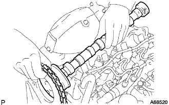
Separate the camshaft timing gear together with the chain in one piece, and remove the camshaft.