INSTALLATION
Removal / installation · Vehicles built from Nov 2005
| 1. INSTALL OIL PAN COVER |

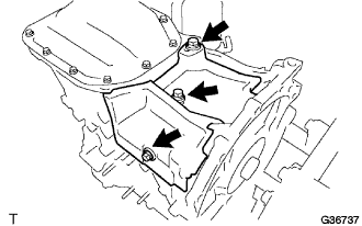  |
Install the oil pan cover with the 3 bolts.
- Torque:
- 5.5 N*m{ 56 kgf*cm , 49 ft.*lbf }
| 2. INSTALL ENGINE OIL LEVEL SENSOR |
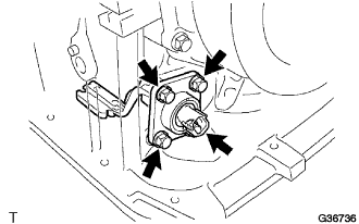 |
Install the engine oil level sensor with the 4 bolts.
- Torque:
- 7.0 N*m{ 71 kgf*cm , 62 ft.*lbf }
| 3. INSTALL CRANKSHAFT POSITION SENSOR |
Install the crankshaft position sensor with the bolt.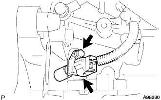
- Torque:
- 8.0 N*m{ 82 kgf*cm , 71 ft.*lbf }
| 4. INSTALL CYLINDER BLOCK SIDE COVER |
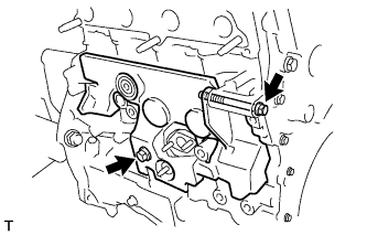 |
Install the cylinder block side cover with the 2 bolts.
- Torque:
- 12 N*m{ 117 kgf*cm , 102 ft.*lbf }
| 5. INSTALL EXHAUST MANIFOLD |
Install a new gasket, then install the exhaust manifold with turbocharger with 5 nuts.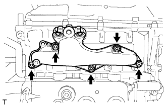
- Torque:
- 43 N*m{ 438 kgf*cm , 32 ft.*lbf }
Install the exhaust manifold heat insulator No. 1 with the 2 bolts.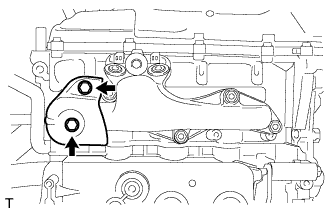
- Torque:
- 6.0 N*m{ 61 kgf*cm , 53 ft.*lbf }
Install the manifold stay with the 2 bolts.
- Torque:
- 37 N*m{ 377 kgf*cm , 27 ft.*lbf }
| 6. INSTALL TURBO OIL OUTLET PIPE |
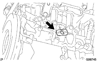 |
Install a new gasket onto the cylinder block.
Provisionally install the turbo oil outlet pipe with 2 new nuts.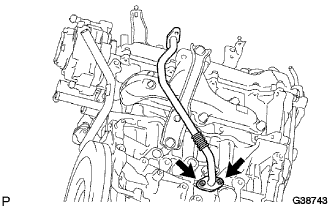
| 7. INSTALL TURBOCHARGER SUB-ASSEMBLY |
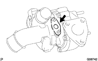 |
Install a new gasket onto the turbocharger.
Install a new gasket onto the exhaust manifold.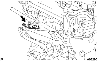
Install the turbocharger with the 3 nuts.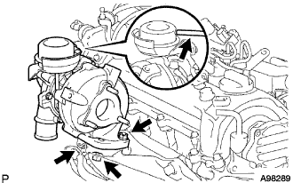
- Torque:
- 53 N*m{ 540 kgf*cm , 39 ft.*lbf }
Connect the vacuum hose to the turbocharger.
Tighten 2 new nuts B.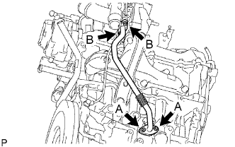
- Torque:
- 11 N*m{ 110 kgf*cm , 8 ft.*lbf }
Tighten 2 new nuts A.
- Torque:
- 14 N*m{ 140 kgf*cm , 10 ft.*lbf }
| 8. INSTALL TURBO OIL INLET PIPE |
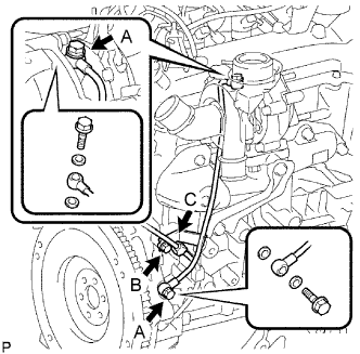 |
Install 4 new gaskets and the turbo oil inlet pipe with 2 union bolts A.
- Torque:
- 24 N*m{ 245 kgf*cm , 18 ft.*lbf }
Tighten bolt B.
- Torque:
- 11 N*m{ 110 kgf*cm , 8 ft.*lbf }
Install wire harness clamp C.
| 9. INSTALL EXHAUST MANIFOLD CONVERTER SUB-ASSEMBLY |
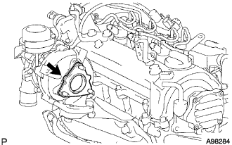 |
Install a new gasket onto the turbocharger.
Temporarily install the exhaust manifold converter with 3 new nuts A.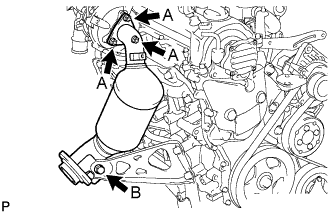
Provisionally install the manifold support bracket with the bolt B.
Tighten 3 nuts A.
- Torque:
- 26 N*m{ 265 kgf*cm , 19 ft.*lbf }
Tighten bolt B.
- Torque:
- 37 N*m{ 375 kgf*cm , 27 ft.*lbf }
| 10. INSTALL TURBO INSULATOR NO. 1 |
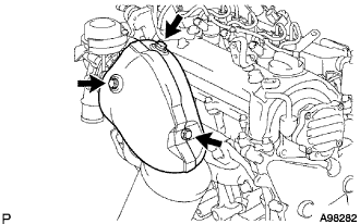 |
Install the turbo insulator No.1 with 3 bolts.
- Torque:
- 6 N*m{ 60 kgf*cm , 53 in.*lbf }
| 11. INSTALL CYLINDER HEAD COVER NO.2 |
| 12. INSTALL CONNECTOR TO VACUUM RESERVOIR TUBE |
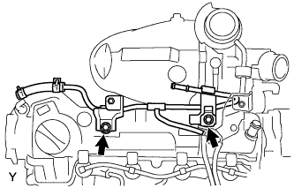 |
Install the connector to vacuum reservoir tube with the 2 bolts.
- Torque:
- 13 N*m{ 133 kgf*cm , 10 ft.*lbf }
| 13. INSTALL ENGINE COVER BRACKET NO. 3 |
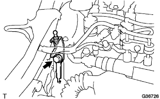 |
Install the engine cover bracket with the 2 bolts.
- Torque:
- 11 N*m{ 112 kgf*cm , 8 ft.*lbf }
Connect the vacuum hose.
| 14. INSTALL DIESEL ENGINE ENGINE COOLANT TEMPERATURE SENSOR |
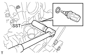 |
Using SST, install the engine coolant temperature sensor.
- SST
- 09817-33190
- Torque:
- 20 N*m{ 204 kgf*cm , 15 ft.*lbf }
| 15. INSTALL INJECTION SUPPLY PUMP ASSEMBLY |
- NOTICE:
- When installing, clean the seal surfaces of the fuel inlet pipe, supply pump and common rail.
Apply a light coat of engine oil to a new O-ring.
Install the O-ring onto the supply pump.
Install the supply pump drive coupling onto the supply pump drive shaft.
Temporarily install the supply pump with the 3 bolts.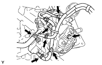
Remove the vinyl bag and rubber band from the supply pump.
Connect the 2 connectors.
Connect the 3 fuel hoses.
| 16. INSTALL INJECTOR ASSEMBLY |
 |
- NOTICE:
- When installing, clean the sealing surface of the injector, injection pipe and common rail.
- When replacing the injectors, the injection pipes must also be replaced.
- Replace the injection pipe with a new one when the injection pipe has been removed and reinstalled more than 5 times.
- Replace the injector with one with the same part number and install it onto the cylinder.
- When installing, clean the sealing surface of the injector, injection pipe and common rail.
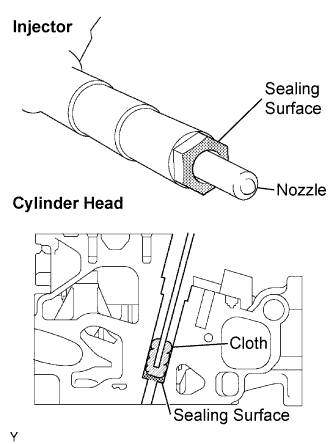
Using a cloth and solvent, wipe away any carbon from the sealing surface of the injector and injector installation hole, as shown in the illustration.
- NOTICE:
- Do not damage the sealing surface.
- Do not touch the injector nozzle.
- Do not damage the sealing surface.
Install 4 new nozzle seats onto the cylinder head.
Install the injector onto the cylinder head.
- NOTICE:
- Fit the injectors into the seats.
Install the 4 nozzle holder clamp seats onto the cylinder head.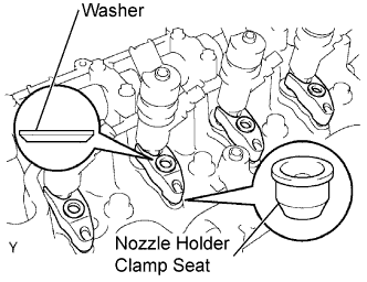
Install the 4 nozzle holder clamps onto the injectors.
Set the washer on the nozzle holder clamp, as shown illustration.
Temporarily tighten the 4 nozzle holder clamp bolts.
Temporarily install the 4 injection pipes onto the injector and common rail.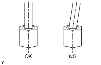
- NOTICE:
- Install the pipe and union nut vertically, not at a tilt.
Tighten the 4 nozzle holder clamp bolts.
- Torque:
- 26 N*m{ 265 kgf*cm , 19 in.*lbf }
Using SST, tighten the injection pipe union nut of the injection pipe on the common rail side.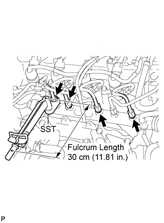
- SST
- 09023-38401
- Torque:
- With SST:
- 23 N*m{ 235 kgf*cm , 17 in.*lbf }
- Without SST:
- 25 N*m{ 255 kgf*cm , 18 in.*lbf }
- HINT:
- Use a torque wrench with a fulcrum length of 30 cm (11.81 in.).
- After the injection pipe has been reassembled, check that the used pipe has no deflection and is installed properly, then replace the used pipe with a new one.
- Use a torque wrench with a fulcrum length of 30 cm (11.81 in.).
Using a spanner (13 mm), hold the injector steadily, and using SST, tighten the injection pipe union nut of the injection pipe on the injector side.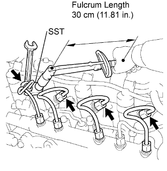
- SST
- 09023-38401
- Torque:
- With SST:
- 23 N*m{ 235 kgf*cm , 17 in.*lbf }
- Without SST:
- 25 N*m{ 255 kgf*cm , 18 in.*lbf }
- HINT:
- Use a torque wrench with a fulcrum length of 30 cm (11.81 in.).
- After the injection pipe has been reassembled, check that the used pipe has no deflection and is installed properly, then replace the used pipe with a new one.
- Use a torque wrench with a fulcrum length of 30 cm (11.81 in.).
Connect the 4 injector connectors.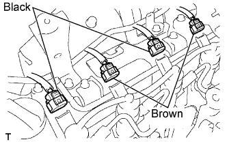
- NOTICE:
- Connect the black connector of the injector to injector No. 1 and No. 3, and brown connector to No. 2 and No. 4.
| 17. INSTALL NOZZLE LEAKAGE PIPE ASSEMBLY |
 |
- NOTICE:
- Never reuse the nozzle leakage pipe once it has been removed from the injectors and supply pump.
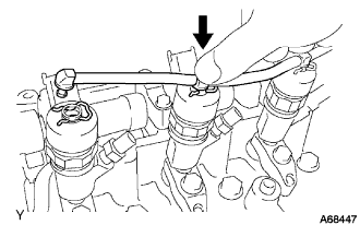
- Push the nozzle leakage pipe until it makes a click sound.
- Never reuse the nozzle leakage pipe once it has been removed from the injectors and supply pump.
Install 5 new retainer springs onto the injectors and supply pump.
Push the new nozzle leakage pipe into each injector and supply pump.
| 18. INSTALL COMMON RAIL ASSEMBLY |
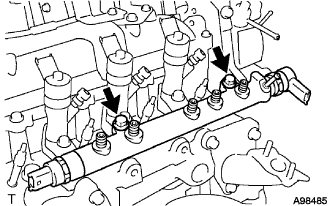 |
Install the common rail assembly
Connect the fuel hose.
Install the common rail with 2 bolts.
- Torque:
- 26 N*m{ 265 kgf*cm , 19 in.*lbf }
| 19. INSTALL FUEL INLET PIPE SUB-ASSEMBLY |
|
|
- NOTICE:
- When replacing the common rail, the fuel inlet pipe must also be replaced.
- Replace the fuel inlet pipe with a new one when the fuel inlet pipe has been removed and reinstalled more than 5 times.
- When replacing the common rail, the fuel inlet pipe must also be replaced.
Temporarily install the fuel inlet pipe onto the supply pump and common rail.
- NOTICE:
- Install the pipe and union nut vertically, not at a tilt.
Using SST, tighten the fuel inlet pipe union nut of the fuel inlet pipe on the common rail side.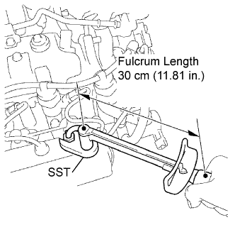
- SST
- 09023-38401
- Torque:
- With SST:
- 23 N*m{ 235 kgf*cm , 17 in.*lbf }
- Without SST:
- 25 N*m{ 255 kgf*cm , 18 in.*lbf }
- HINT:
- Use a torque wrench with a fulcrum length of 30 cm (11.81 in.).
- After the fuel inlet pipe has been reassembled, check that the used pipe has no deflection and is installed properly.
If it has deflection or could not be installed properly, replace the used pipe with a new one.
- Use a torque wrench with a fulcrum length of 30 cm (11.81 in.).
Using a spanner (17 mm), hold the supply pump steady, and using SST, tighten the fuel inlet pipe union nut of the fuel inlet pipe on the supply pump side.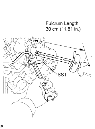
- SST
- 09023-38401
- Torque:
- With SST:
- 23 N*m{ 235 kgf*cm , 17 in.*lbf }
- Without SST:
- 25 N*m{ 255 kgf*cm , 18 in.*lbf }
- HINT:
- Use a torque wrench with a fulcrum length of 30 cm (11.81 in.).
- After the fuel inlet pipe has been reassembled, check that the used pipe has no deflection and is installed properly.
If it has deflection or could not be installed properly, replace the used pipe with a new one.
- Use a torque wrench with a fulcrum length of 30 cm (11.81 in.).
| 20. INSTALL INJECTION PIPE SUB-ASSEMBLY No. 1 |
|
|
- CAUTION:
- When replacing the common rail, the injection pipes must also be replaced.
- Replace the injection pipe with a new one when the injection pipe has been removed and reinstalled more than 5 times.
- When replacing the common rail, the injection pipes must also be replaced.
Temporarily install the 4 injection pipes onto the injector and common rail.
- NOTICE:
- Install the pipe and union nut vertically, not at a tilt.
Using SST, tighten the injection pipe union nut of the injection pipe on the common rail side.
- SST
- 09023-38401
- Torque:
- With SST:
- 23 N*m{ 235 kgf*cm , 17 in.*lbf }
- Without SST:
- 25 N*m{ 255 kgf*cm , 18 in.*lbf }
- HINT:
- Use a torque wrench with a fulcrum length of 30 cm (11.81 in.).
- After the fuel inlet pipe has been reassembled, check that the used pipe has no deflection and is installed properly.
If it has deflection or could not be installed properly, replace the used pipe with a new one.
- Use a torque wrench with a fulcrum length of 30 cm (11.81 in.).
Using a spanner (13 mm), hold the injector steady, and using SST, tighten the injection pipe union nut of the injection pipe with a new one.
- SST
- 09023-38401
- Torque:
- With SST:
- 23 N*m{ 235 kgf*cm , 17 in.*lbf }
- Without SST:
- 25 N*m{ 255 kgf*cm , 18 in.*lbf }
- HINT:
- Use a torque wrench with a fulcrum length of 30 cm (11.81 in.).
- After the fuel inlet pipe has been reassembled, check that the used pipe has no deflection and is installed properly.
If it has deflection or could not be installed properly, replace the used pipe with a new one.
- Use a torque wrench with a fulcrum length of 30 cm (11.81 in.).
| 21. INSTALL INJECTION PIPE SUB-ASSEMBLY NO. 2 |
- HINT:
- Perform the same procedure as for injection pipe No. 1.
| 22. INSTALL INJECTION PIPE SUB-ASSEMBLY NO. 3 |
- HINT:
- Perform the same procedure as for injection pipe No. 1.
| 23. INSTALL INJECTION PIPE SUB-ASSEMBLY NO. 4 |
- HINT:
- Perform the same procedure as for injection pipe No. 1.
| 24. INSTALL INJECTION PIPE CLAMP NO.1 |
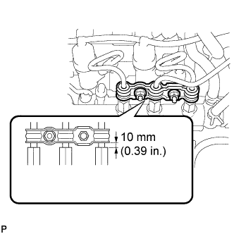 |
Install injection pipe clamp No. 1 with the 2 nuts as shown in the illustration.
- Torque:
- 9.0 N*m{ 92 kgf*cm , 80 in.*lbf }
| 25. INSTALL INJECTION PIPE CLAMP NO. 2 |
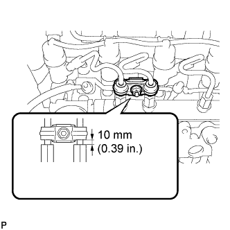 |
Install injection pipe clamp No. 2 with the nut as shown in the illustration.
- Torque:
- 9.0 N*m{ 92 kgf*cm , 80 in.*lbf }
| 26. INSTALL GLOW PLUG ASSEMBLY |
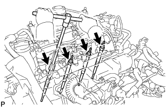 |
Clean the glow plug installation holes in the cylinder head.
Using a 10 mm deep socket wrench , install the 4 glow plugs.
- Torque:
- :
- 13 N*m{ 127 kgf*cm , 9 ft.*lbf }
| 27. INSTALL GLOW PLUG NO.1 CONNECTOR |
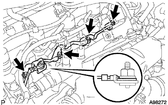 |
Install glow plug connector No. 1 with the 4 nuts.
- Torque:
- 1.6 N*m{ 15 kgf*cm , 14 in.*lbf }
Connect the glow terminal with the nut.
- Torque:
- 3.8 N*m{ 40 kgf*cm , 34 in.*lbf }
- NOTICE:
- Install the glow terminal in the correct direction.
Install the 5 screw grommets.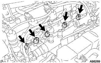
- NOTICE:
- Push the screw grommet into the threaded portion of the glow plug by hand, and then turn it clockwise.
| 28. INSTALL ENGINE OIL PRESSURE SWITCH ASSEMBLY |
| 29. INSTALL WATER BY-PASS PIPE NO. 1 |
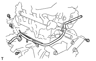 |
Install a new gasket, then install water by-pass pipe No. 1 with the 2 bolts.
- Torque:
- 9.0 N*m{ 92 kgf*cm , 80 ft.*lbf }
| 30. INSTALL EGR PIPE NO. 1 HOSE |
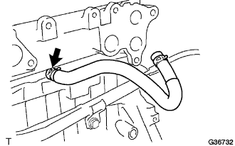 |
Install the EGR pipe No. 1 hose.
| 31. INSTALL OIL COOLER HOSE SUB-ASSEMBLY |
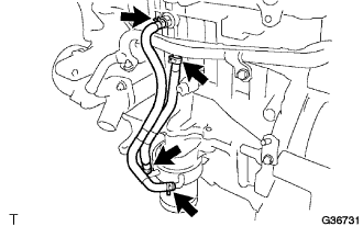 |
Install the oil cooler hose.
| 32. INSTALL EGR PIPE CONNECTOR |
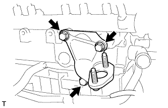 |
Install a new gasket, then install the EGR pipe connector with the 3 bolts.
- Torque:
- 20 N*m{ 204 kgf*cm , 15 ft.*lbf }
| 33. INSTALL INTAKE AIR CONNECTOR |
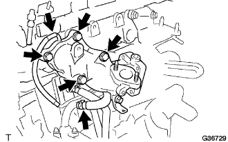 |
Install a new gasket, then install the intake air connector with the 4 bolts.
- Torque:
- 20 N*m{ 204 kgf*cm , 15 ft.*lbf }
Connect the vacuum hose and water hose.
| 34. INSTALL EGR VALVE ASSEMBLY |
Install a new gaskets.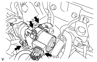
Install the EGR valve assembly with the 2 nuts.
- Torque:
- 20 N*m{ 204 kgf*cm , 15 ft.*lbf }
Connect the EGR valve connector and hose.
| 35. INSTALL VACUUM REGULATING VALVE ASSEMBLY |
Install the vacuum regulating valve with the 3 bolts.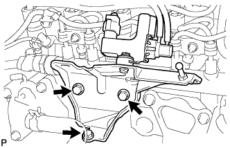
- Torque:
- 20 N*m{ 204 kgf*cm , 15 in.*lbf }
Connect the vacuum regulating valve connector and 2 vacuum hoses.
| 36. INSTALL EGR COOLER ASSEMBLY |
Install 2 new gaskets.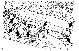
Temporarily install the EGR cooler assembly with the bolt and 4 nuts, in the order described below.
Tighten bolt B.
- Torque:
- 11 N*m{ 112 kgf*cm , 8 ft.*lbf }
Tighten the 2 A nuts.
- Torque:
- 11 N*m{ 112 kgf*cm , 8 ft.*lbf }
Tighten the 2 C nuts.
- Torque:
- 20 N*m{ 204 kgf*cm , 15 ft.*lbf }
Connect the 2 water by-pass hoses.
| 37. INSTALL OIL LEVEL GAGE GUIDE |
Install the oil level gage with the bolt.
| 38. INSTALL VACUUM PUMP ASSEMBLY |
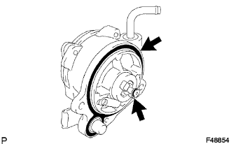 |
Coat 2 new O-rings with engine oil, and place them onto the vacuum pump.
Apply engine oil to the oil pipe at the tip of the vacuum pump.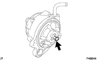
Install the vacuum pump so that the coupling teeth A on the side of the vacuum pump can engage with the tip groove of camshaft B.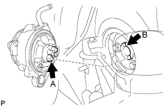
Install 2 new bolts onto the vacuum pump.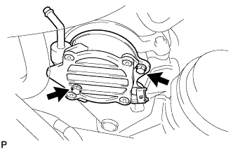
- Torque:
- 21 N*m{ 214 kgf*cm , 16 ft.*lbf }
Connect the vacuum hose with the clip to the vacuum pump.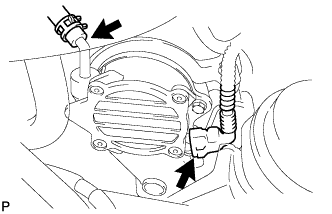
Connect the cam position sensor connector.
| 39. INSTALL TIMING CHAIN COVER NO.2 |
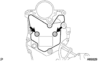 |
Install the timing cover No. 2 with the 2 bolts.
- Torque:
- 5.5 N*m{ 56 kgf*cm , 49 in.*lbf }
| 40. INSTALL GENERATOR ASSEMBLY |
| 41. INSTALL CYLINDER HEAD COVER NO. 2 |
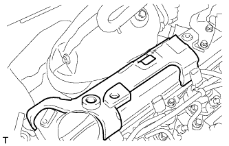 |
| 42. INSTALL ENGINE WIRE |
| 43. INSTALL CRANKSHAFT POSITION SENSOR |
Install the crankshaft position sensor with the bolt.
- Torque:
- 8.0 N*m{ 82 kgf*cm , 71 in.*lbf }
Connect the crankshaft position sensor connector.
| 44. INSTALL FLYWHEEL SUB-ASSEMBLY |
Install the crankshaft position sensor plate.
Hold the crankshaft with SST.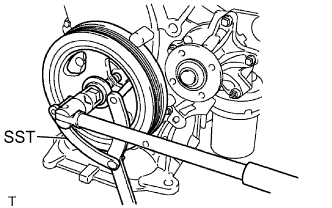
- SST
- 09960-10010
(09962-01000, 09963-01000)
Apply adhesive to the 2 or 3 end threads of the bolts.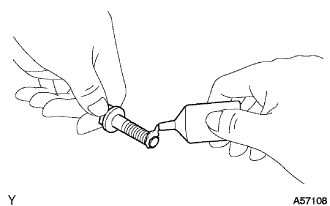
Install the flywheel with the 6 bolts in the order shown in the illustration.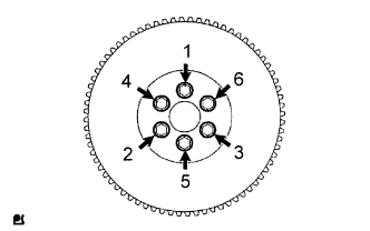
| 45. INSTALL CLUTCH DISC ASSEMBLY |
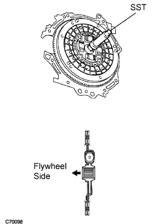 |
Insert SST into the clutch disc assembly, then insert them both into the flywheel sub-assembly.
- SST
- 09301-00110
- NOTICE:
- Insert clutch disc assembly in the correct direction.
| 46. INSTALL CLUTCH COVER ASSEMBLY |
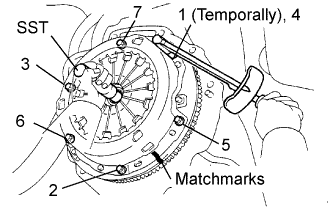 |
Align the matchmark on the clutch cover assembly with that on the flywheel sub-assembly.
Following the procedures shown in the illustration, tighten the 6 bolts in order, starting with the bolt located near the knock pin at the top.
- Torque:
- 19 N*m{ 195 kgf*cm , 14 ft.*lbf }
- HINT:
- Following the order in the illustration, tighten the bolts evenly one at a time.
- Move SST up and down, right and left lightly after checking that the disc is in the center, and tighten the bolts.
- Following the order in the illustration, tighten the bolts evenly one at a time.
- SST
- 09301-00210
| 47. INSTALL MANUAL TRANSAXLE ASSEMBLY (for Manual Transaxle) |
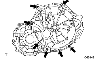 |
Align the input shaft with the clutch disc and install the manual transaxle onto the engine.
Install the 7 bolts.
- Torque:
- 33 N*m{ 336 kgf*cm , 24 ft.*lbf }
| 48. INSTALL MULTI-MODE MANUAL TRANSAXLE ASSEMBLY (for Multi-Mode Manual Transaxle) |
Align the input shaft with the clutch disc and install the manual transaxle onto the engine.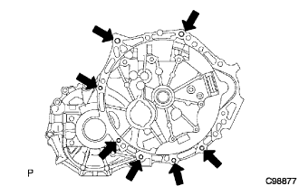
Install the 7 bolts.
- Torque:
- 33 N*m{ 336 kgf*cm , 24 ft.*lbf }
- NOTICE:
- Insert dowel pins into the dowel holes securely so that the end face of the transaxle assembly fits close against the engine assembly before tightening the bolts between the engine and transaxle.
- Make sure that the dowel pins are not loose, bent, damaged or scratched and then install the transaxle onto the engine with the contact surfaces of the engine and transaxle flat against each other.
- Insert dowel pins into the dowel holes securely so that the end face of the transaxle assembly fits close against the engine assembly before tightening the bolts between the engine and transaxle.
| 49. INSTALL STATER ASSEMBLY (for Manual Transaxle) |
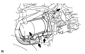 |
Install the starter assembly with the 2 bolts.
- Torque:
- 37 N*m{ 377 kgf*cm , 27 ft.*lbf }
Connect the connector.
Connect terminal 30 with the nut.
- Torque:
- 9.8 N*m{ 100 kgf*cm , 87 in.*lbf }
Close the terminal cap.
| 50. INSTALL STARTER ASSEMBLY (for Multi-Mode Manual Transaxle) |
|
|
Install the starter assembly with the 2 bolts.
- Torque:
- 37 N*m{ 377 kgf*cm , 27 ft.*lbf }
Connect the connector.
Connect terminal 30 with the nut.
- Torque:
- 9.8 N*m{ 100 kgf*cm , 87 in.*lbf }
Close the terminal cap.
Install the wire harness bracket with the bolt.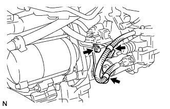
- Torque:
- 8.0 N*m{ 82 kgf*cm , 71 in.*lbf }
Install the harness clamp.
| 51. INSTALL FRONT SUSPENSION CROSSMEMBER SUB-ASSEMBLY |
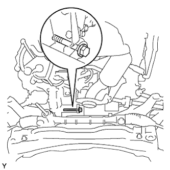 |
Install the engine moving control rod with the through bolt.
- Torque:
- 120 N*m{ 1,224 kgf*cm , 89 ft.*lbf }
Remove the 2 bolts and remove the 2 engine hangers.
| 52. INSTALL ENGINE ASSEMBLY WITH TRANSAXLE |
Set the engine assembly with transaxle and front suspension crossmember on the engine lifter.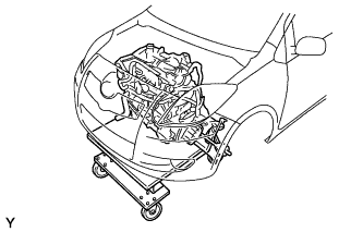
- SST
- 09670-00010
Operate the engine lifter and lift the engine assembly with transaxle and front suspension crossmember to position where the engine mounting insulators RH and LH can be installed.
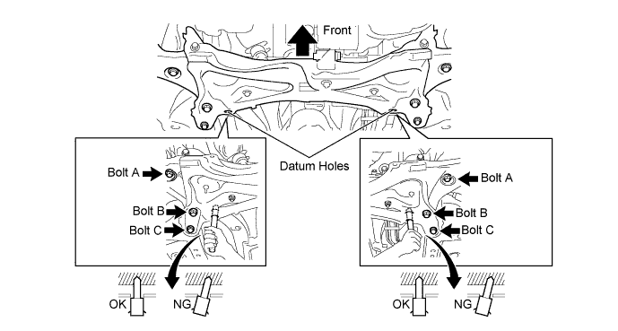
Install the engine mounting insulator LH with the through bolt and nut.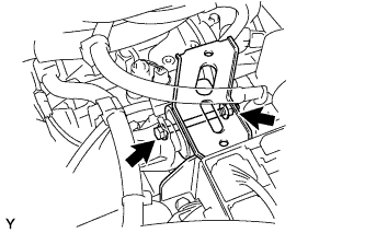
- Torque:
- 52 N*m{ 530 kgf*cm , 38 in.*lbf }
Install the engine mounting insulator RH with the 7 bolts and nut.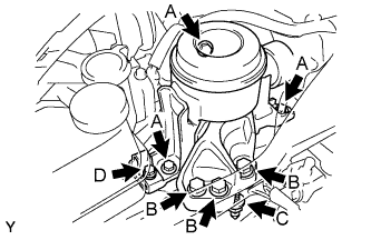
- Torque:
- 52 N*m{ 530 kgf*cm , 38 ft.*lbf } for bolt A
- 88 N*m{ 897 kgf*cm , 65 ft.*lbf } for bolt B
- 52 N*m{ 530 kgf*cm , 38 ft.*lbf } for nut C
- 20 N*m{ 199 kgf*cm , 14 ft.*lbf } for bolt D
| 53. INSTALL CLUTCH ACCUMULATOR ASSEMBLY (for Manual Transaxle) |
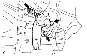 |
Install the clutch accumulator with the 2 bolts and nut.
- Torque:
- 37 N*m{ 380 kgf*cm , 28 ft.*lbf } for bolt
- 5.0 N*m{ 51 kgf*cm , 44 in.*lbf } for nut
Install the flexible hose bracket with the bolt.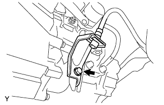
- Torque:
- 19 N*m{ 194 kgf*cm , 14 ft.*lbf }
Using SST, install the accumulator to flexible hose tube.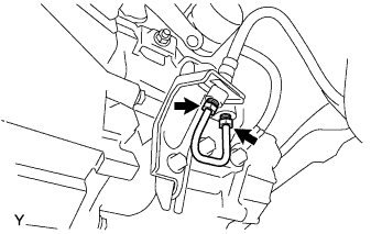
- SST
- 09023-00101
- Torque:
- 15 N*m{ 155 kgf*cm , 11 ft.*lbf }
Using SST, connect the release cylinder to accumulator tube.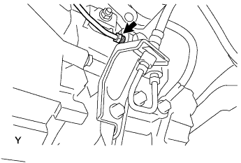
- SST
- 09023-00101
- Torque:
- 15 N*m{ 155 kgf*cm , 11 ft.*lbf }
| 54. INSTALL CLUTCH RELEASE CYLINDER ASSEMBLY (for Manual Transaxle) |
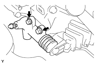 |
Install the clutch release cylinder with the 2 bolts.
- Torque:
- 12 N*m{ 120 kgf*cm , 8.7 ft.*lbf }
| 55. INSTALL FRONT DRIVE SHAFT ASSEMBLY LH |
Coat the spline of the inboard joint with gear oil.
Align the inboard joint splines and install the drive shaft with a screwdriver and hammer.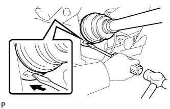
- NOTICE:
- Face the cut area of the front drive inboard joint hole snap ring downward.
- Do not damage the oil seal.
- Do not damage the inboard joint boot.
- Face the cut area of the front drive inboard joint hole snap ring downward.
- HINT:
- Confirm whether the drive shaft is securely driven in by checking the reaction force and sound.
| 56. INSTALL FRONT DRIVE SHAFT ASSEMBLY RH |
- HINT:
- The installation procedure for the RH side is the same as that for the LH side.
| 57. INSTALL FRONT AXLE ASSEMBLY LH |
Push the front axle out of the vehicle to align the spline of the drive shaft with the front axle and insert the front axle.
- NOTICE:
- Do not push the front axle further out of the vehicle than is necessary.
- Do not damage the outboard joint boot.
- Check for any foreign matter on the speed sensor rotor and insertion part.
- Do not damage the speed sensor rotor.
- Do not push the front axle further out of the vehicle than is necessary.
| 58. INSTALL FRONT AXLE ASSEMBLY RH |
- HINT:
- Perform the same procedure as above on the opposite side.
| 59. INSTALL FRONT SUSPENSION ARM SUB ASSEMBLY LOWER NO. 1 LH |
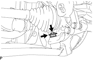 |
Install the lower arm onto the steering knuckle with a new castle nut.
- Torque:
- 98 N*m{ 1,000 kgf*cm , 72 ft.*lbf }
- NOTICE:
- If the holes for the clip are not aligned, tighten the nut by a further turn of up to 60°.
Install a new clip.
| 60. REMOVE FRONT SUSPENSION ARM SUB ASSEMBLY LOWER NO. 1 RH |
- HINT:
- Perform the same procedure as above on the opposite side.
| 61. INSTALL TIE ROD END SUB ASSEMBLY LH |
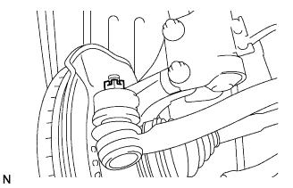 |
Install the tie rod end onto the steering knuckle with a new castle nut.
- Torque:
- 49 N*m{ 500 kgf*cm , 36 ft.*lbf }
- NOTICE:
- If the holes for the clip are not aligned, tighten the nut by a further turn of up to 60°.
Install a new cotter pin.
| 62. INSTALL TIE ROD END SUB-ASSEMBLY RH |
- HINT:
- Perform the same procedure as above on the opposite side.
| 63. INSTALL FRONT STABILIZER LINK ASSEMBLY LH |
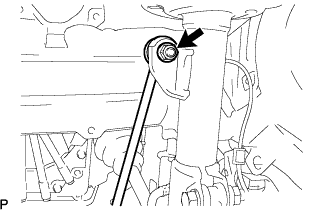 |
Install the stabilizer link with the nut.
- Torque:
- 74 N*m{ 755 kgf*cm , 55 ft.*lbf }
- HINT:
- If the ball joint turns together with the nut, use a socket hexagon wrench 6 to hold the stud.
| 64. INSTALL FRONT STABILIZER LINK ASSEMBLY RH |
- HINT:
- Perform the same procedure as above on the opposite side.
| 65. INSTALL FRONT AXLE SHAFT LH NUT |
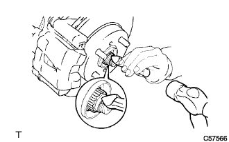 |
Using a 30 mm socket wrench, install a new axle hub nut.
- Torque:
- 216 N*m{ 2,203 kgf*cm , 160 ft.*lbf }
Using a chisel and hammer, caulk the axle hub nut.
| 66. INSTALL FRONT AXLE HUB RH NUT |
- HINT:
- Perform the same procedure as above on the opposite side.
| 67. INSTALL FRONT SPEED SENSOR |
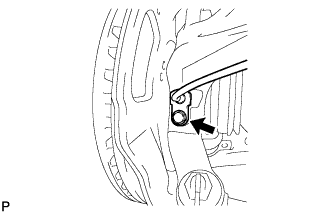 |
Install the speed sensor onto the steering knuckle with the bolt.
- Torque:
- 8.5 N*m{ 87 kgf*cm , 75 in.*lbf }
- NOTICE:
- Check that the speed sensor tip and installation portion are free of foreign matter.
- Install the speed sensor without turning it from its original installation angle.
- Check that the speed sensor tip and installation portion are free of foreign matter.
Install the flexible hose and speed sensor with the bolt.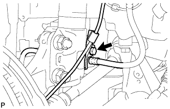
- Torque:
- 29 N*m{ 300 kgf*cm , 22 ft.*lbf }
- NOTICE:
- Install the flexible hose and speed sensor without twisting them.
| 68. INSTALL EXHAUST PIPE ASSEMBLY FRONT |
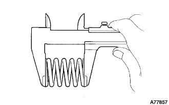 |
Check the free length.
Using vernier calipers, measure the free length of the compression spring.
- Minimum length:
- 40.5mm (1.594 in.)
Using a wooden block and plastic-hammer, tap in a new gasket until it is flush with the exhaust manifold converter.
- NOTICE:
- Make sure that the gasket is in the correct direction when installing it.
- Do not reuse a removed gasket.
- Never push the gasket into the exhaust manifold converter by installing the exhaust pipe front onto the exhaust manifold converter.
- Make sure that the gasket is in the correct direction when installing it.
Install the exhaust pipe front onto the 3 exhaust pipe supports.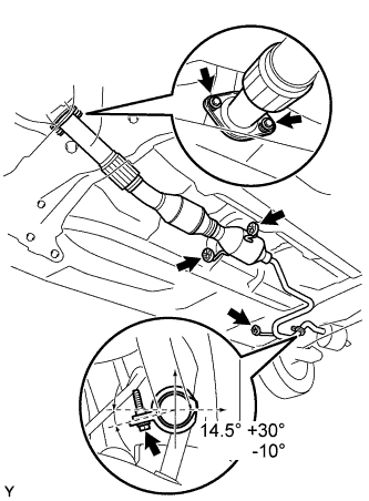
Install a new gasket onto the exhaust pipe front.
Install a new clamp with the bolt as shown in the illustration.
- Torque:
- 32 N*m{ 326 kgf*cm , 24 ft.*lbf }
- NOTICE:
- Do not reuse the removed gasket and clamp.
- Make sure that the pipe clamp is at the correct angle when installing it.
- Do not reuse the removed gasket and clamp.
Install the exhaust pipe front with the 2 compression springs and 2 bolts.
- Torque:
- 43 N*m{ 440 kgf*cm , 32 ft.*lbf }
| 69. INSTALL STEERING SLIDING YOKE SUB-ASSEMBLY |
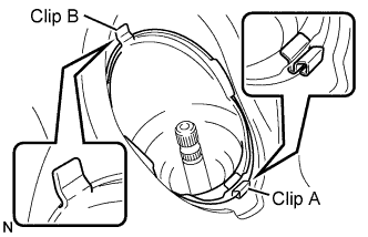 |
Install clip B onto the vehicle body and install the steering column hole cover onto the vehicle body with clip A.
- NOTICE:
- Fit the lip of the steering column hole cover correctly onto the dash panel.
| 70. INSTALL STEERING SLIDING YOKE SUB-ASSEMBLY |
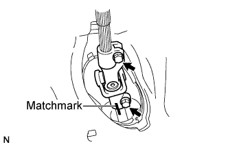 |
Align the matchmarks and install steering intermediate shaft onto the steering gear with the 2 bolts.
- Torque:
- 28 N*m{ 286 kgf*cm , 21 ft.*lbf }
| 71. INSTALL COLUMN HOLE COVER SILENCER SHEET |
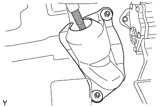 |
Install the column hole cover silencer sheet with the 2 clips.
| 72. INSTALL ENGINE WIRE |
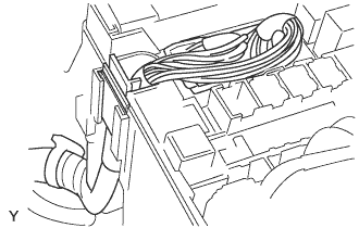 |
Connect the 2 engine wire harness connectors and wire harness clamp to the engine room junction block.
Connect the engine wire harness connector to the ECM.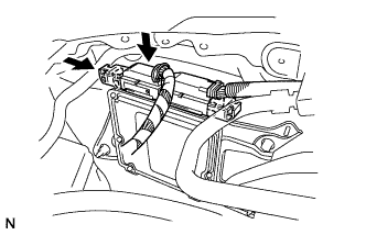
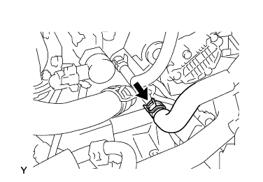
| 73. INSTALL HEATER OUTLET WATER HOSE |
 |
| 74. INSTALL HEATER INLET WATER HOSE |
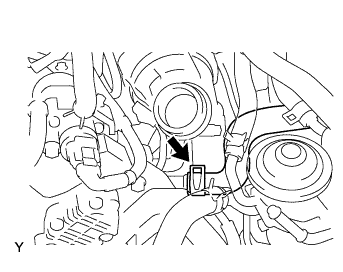 |
| 75. INSTALL WATER BY-PASS HOSE NO. 5 |
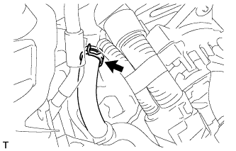 |
| 76. INSTALL RADIATOR HOSE NO. 1 |
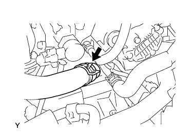 |
| 77. REMOVE RADIATOR HOSE NO. 2 |
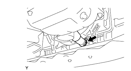 |
| 78. INSTALL FUEL HOSE NO. 1 |
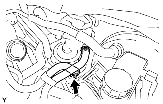 |
Connect fuel hose No. 1 to the supply pump.
| 79. INSTALL FUEL HOSE NO. 2 |
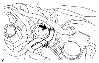 |
Connect fuel hose No. 2 to the supply pump.
| 80. INSTALL UNION TO CONNECTOR TUBE HOSE |
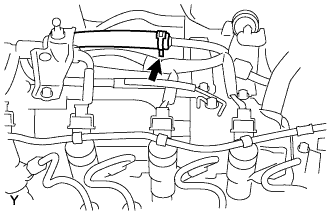 |
Connect the union to connector tube hose.
| 81. CONNECT TURBO PRESSURE HOSE |
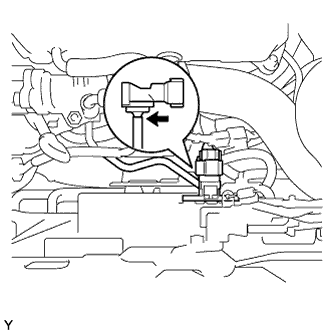 |
| 82. CONNECT VACUUM TRANSMITTING HOSE NO. 1 ASSEMBLY |
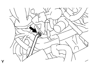 |
| 83. CONNECT TRANSMISSION CONTROL CABLE ASSEMBLY (for Manual Transaxle) |
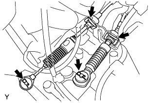 |
Connect the 2 cables and install the 2 clips.
Install 2 new clips onto the control cable bracket.
| 84. INSTALL AIR TUBE NO.1 (for C53) |
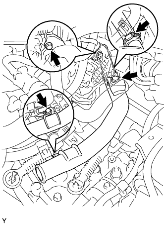 |
Install air tube No. 1 with the 2 bolts.
- Torque:
- 20 N*m{ 199 kgf*cm , 14 ft.*lbf }
Install the wire harness bracket with the bolt.
- Torque:
- 3.5 N*m{ 36 kgf*cm , 31 in.*lbf }
Connect air hose No. 1 with the clamp.
- Torque:
- 6.0 N*m{ 61 kgf*cm , 53 in.*lbf }
| 85. INSTALL AIR HOSE NO. 2 |
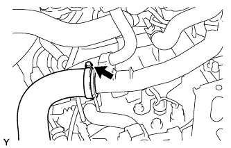 |
Connect air hose No. 2 to air tube No. 1.
| 86. INSTALL AIR HOSE NO. 3 |
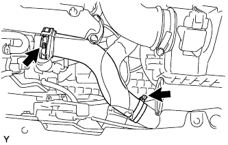 |
Install air hose No. 3.
| 87. INSTALL WITH PULLEY COMPRESSOR ASSEMBLY (w/ Air Conditioning System) |
| 88. INSTALL FAN AND GENERATOR V BELT |
Temporarily install the fan and generator V belt onto each pulley.
- NOTICE:
- Before installing the V belt, check each pulley for any kind of liquid and chips.
- Before installing the V belt, check each pulley for any kind of liquid and chips.
- Check that the ribs of the V belt are correctly fitted into the grooves of the pulleys.
- Check that the ribs of the V belt are correctly fitted into the grooves of the pulleys.
| 89. ADJUST FAN AND GENERATOR V BELT |
Insert a bar between the generator and the engine. Pull the bar toward the front of the vehicle and adjust the tension.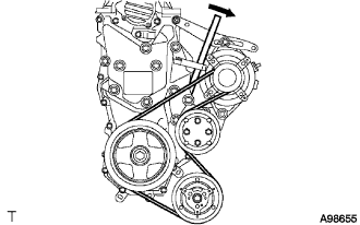
Tighten bolt A, then tighten bolt B.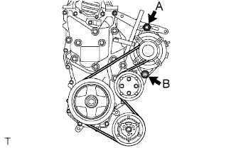
- Torque:
- Bolt A:
- 19 N*m{ 189 kgf*cm , 14 ft.*lbf }
- Bolt B:
- 32 N*m{ 326 kgf*cm , 24 ft.*lbf }
| 90. INSTALL BATTERY CARRIER ASSEMBLY WITH WIRING HARNESS CLAMP |
Install the battery carrier assembly with wiring harness clamp with the 5 bolts.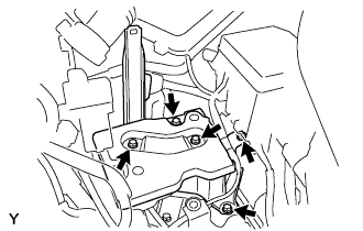
- Torque:
- 17 N*m{ 175 kgf*cm , 13 ft.*lbf }
| 91. INSTALL BATTERY TRAY |
| 92. INSTALL BATTERY |
| 93. INSTALL AIR CLEANER BRACKET |
Install the air cleaner No. 1 bracket with the 3 bolts.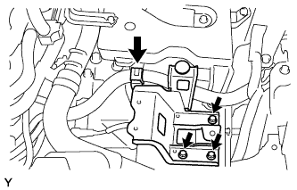
- Torque:
- 20 N*m{ 199 kgf*cm , 14 ft.*lbf }
| 94. INSTALL AIR CLEANER CASE SUB-ASSEMBLY WITH AIR CLEANER INLET |
Install the air cleaner case sub-assembly with air cleaner inlet with the 3 bolts.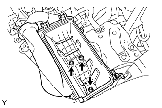
- Torque:
- 7.8 N*m{ 80 kgf*cm , 69 in.*lbf }
| 95. INSTALL AIR CLEANER FILTER ELEMENT SUB-ASSEMBLY |
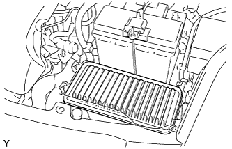 |
Install the air cleaner filter element onto the air cleaner case.
| 96. INSTALL AIR CLEANER CAP SUB-ASSEMBLY WITH HOSE |
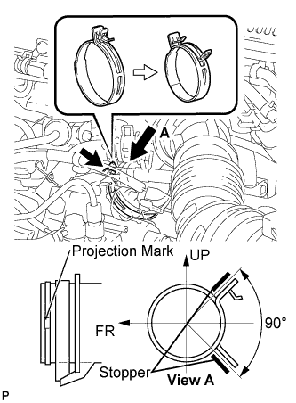 |
Align the matchmarks of air cleaner hose No. 1 and turbocharger, and connect air cleaner hose No. 1 to the turbocharger and fasten air cleaner hose clamp No. 1.
- NOTICE:
- Make sure that the hose clamp is at the correct angle when installing it.
Connect the ventilation hose to the cylinder head cover.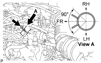
- NOTICE:
- Make sure that the hose clamp is at the correct angle when installing it.
Install the air cleaner cap onto the air cleaner case, then hang the 2 hook clamps.
Fit the wire harness into the air cleaner cap.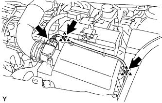
Engage the 2 wire harness clamps.
Connect the mass air flow meter connector.
| 97. INSTALL COWL TOP PANEL OUTER |
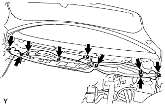 |
Install the cowl top panel outer with the 9 bolts.
- Torque:
- 6.5 N*m{ 66 kgf*cm , 58 in.*lbf }
Install the wire harness.
| 98. INSTALL COWL TO REGISTER DUCT SUB-ASSEMBLY NO. 2 |
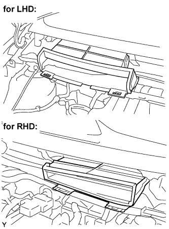 |
Engage the claws, and install cowl top register duct No. 2.
| 99. INSTALL FRONT WIPER MOTOR AND LINK ASSEMBLY |
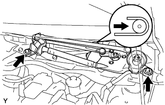 |
Connect the connector.
Slide the wiper link as shown in the illustration and engage the rubber pin with the body.
Install the front wiper motor and link with the 2 bolts.
- Torque:
- 5.5 N*m{ 56 kgf*cm , 49 in.*lbf }
| 100. INSTALL COWL TOP VENTILATOR LOUVER LH (for LHD) |
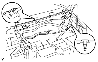 |
Engage the 4 claws and install the cowl top ventilator louver LH.
Install the 2 clips.
| 101. INSTALL COWL TOP VENTILATOR LOUVER SUB-ASSEMBLY (for LHD) |
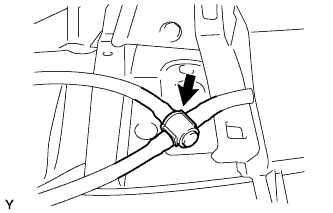 |
Connect the washer hose.
Engage the 11 claws and install the cowl top ventilator louver sub-assembly.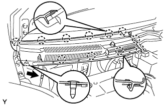
Install the clip.
Connect the washer hose.
Engage the 2 hooks and install cowl top ventilator louver center No. 1.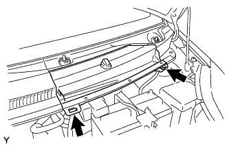
| 102. INSTALL COWL TOP VENTILATOR LOUVER LH (for RHD) |
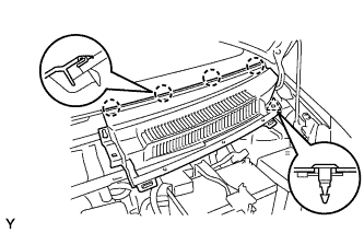 |
Engage the 4 claws and install the cowl top ventilator louver LH.
Install the clip.
| 103. INSTALL COWL TOP VENTILATOR LOUVER SUB-ASSEMBLY (for RHD) |
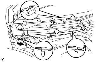 |
Engage the 10 claws and install the cowl top ventilator louver sub-assembly.
Install the clip.
Connect the washer hose.
| 104. INSTALL HOOD TO COWL TOP SEAL |
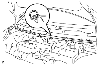 |
Engage the 7 clips and install the hood to cowl top seal.
| 105. INSTALL FRONT WIPER ARM AND BLADE ASSEMBLY LH |
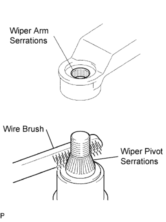 |
Scrape any metal powder off the serrated part of the wiper arm with a round file or the equivalent (when reinstalling).
Clean the wiper pivot serrations with a wire brush.
Operate the wiper, then stop the windshield wiper motor in the automatic stop position.
Align the blade tip with the mark on the windshield glass, as shown in the illustration.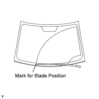
Tighten the nut of the front wiper arm.
- Torque:
- 26 N*m{ 265 kgf*cm , 19 ft.*lbf }
| 106. INSTALL FRONT WIPER ARM AND BLADE ASSEMBLY RH |
|
|
Scrape any metal powder off the serrated part of the wiper arm with a round file or the equivalent (when reinstalling).
Clean the wiper pivot serrations with a wire brush.
Operate the wiper, then stop the windshield wiper motor in the automatic stop position.
Align the blade tip with the mark on the windshield glass, as shown in the illustration.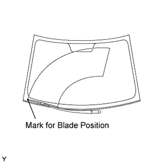
Tighten the nut of the front wiper arm.
- Torque:
- 26 N*m{ 265 kgf*cm , 19 ft.*lbf }
| 107. INSTALL FRONT WIPER ARM HEAD CAP |
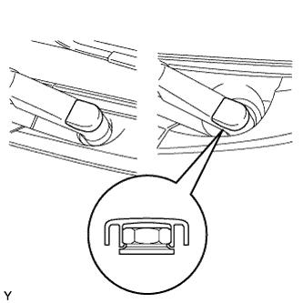 |
Engage the claw and install the 2 front wiper arm head caps.
| 108. ADD MANUAL TRANSAXLE OIL |
| 109. ADD ENGINE OIL |
Fill the engine oil with fresh engine oil.
- Capacity:
Item
Capacity
Drain and refill with oil filter change
4.3 liters (4.5 US qts, 3.8 lmp. qts)
Drain and refill without oil filter change
3.8 liters (4.0 US qts, 3.3 lmp. qts)
Dry fill
4.8 liters (5.1 US qts, 4.2 lmp. qts)
| 110. ADD COOLANT |
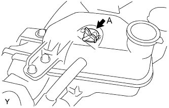 |
Remove air bleed valve A.
Fill the cooling system with coolant up to line B.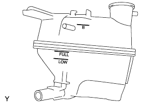
- Capacity:
- 4.7 liters (5.0 US qts, 4.1 lmp. qts)
- HINT:
- Use of improper coolant may damage the engine cooling system.
- Use only Toyota Super Long Life Coolant or similar high quality ethylene glycol based non-silicate, non-amine, non-nitrite, and non-borate engine coolant with long-life hybrid organic acid technology (coolant with long-life hybrid organic acid technology consists of a combination of low phosphates and organic acids).
- Use of improper coolant may damage the engine cooling system.
- NOTICE:
- Do not substitute plain water for engine coolant.
Tighten air bleed valve A.
Install the radiator cap.
Warm up the engine.
Set the air conditioning as follows while warming up the engine.
Item
Manual air conditioning system
Automatic air conditioning system
Set control as follows
Fan speed - Any setting except "OFF"
Temperature - Toward WARM
Air conditioning switch "OFF"
Fan speed - Any setting except "OFF"
Temperature - To the highest temperature
Air conditioning switch "OFF"
"AUTO" switch "OFF"
Run the engine at 3,000 rpm for 5 seconds and idling for 45 seconds alternately.
Do the above operation for 7 minutes or more.
After the engine cools down, check that the coolant level is between LOW and FULL lines.
| 111. INSPECT MANUAL TRANSAXLE OIL LEVEL |
 |
Stop the vehicle in a level place.
Remove the transmission filler plug and the gasket.
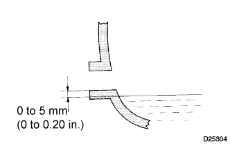
Check that the oil surface is within 5 mm (0.20 in.) of the bottom of the transmission filler plug opening.
- NOTICE:
- Excessively large or small amounts of oil may cause problems.
- After replacing the oil, drive the vehicle and check the oil level again.
- Excessively large or small amounts of oil may cause problems.
Check for oil leakage when the oil level is low.
Install the transmission filler plug and a new gasket.
- Torque:
- 39 N*m{ 400 kgf*cm , 29 ft.*lbf }
| 112. CHECK ENGINE OIL LEVEL |
| 113. CHECK FOR ENGINE COOLANT LEAKAGE |
- CAUTION:
- To avoid the danger of being burned, do not remove the radiator cap sub-assembly while the engine and radiator assembly are still hot. Thermal expansion will cause hot engine coolant and steam to blow out from the radiator assembly.
Fill the radiator assembly with engine coolant, then attach a radiator cap tester.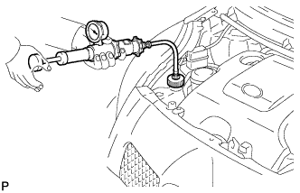
Pump it to 137 kPa (1.4 kgf/cm2, 19.9 psi), then check that the pressure does not drop.
If the pressure drops, check the hoses, radiator assembly and water pump assembly for leakage. If there are no signs or traces of external engine coolant leakage, check the heater core, cylinder block and head.
| 114. CHECK FOR FUEL LEAKAGE |
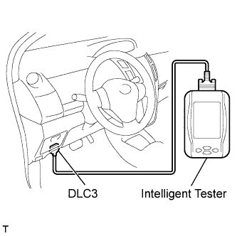 |
Connect an intelligent tester to the DLC3.
Turn the ignition switch on (IG).
Turn the tester on.
Select the following menu items: Powertrain / Engine and ECT / Active Test.
- HINT:
- Fuel pressure inside common rail pressurized to 135 MPa and engine speed increased to 2,000 rpm when ON selected.
- Above conditions preserved while test ON.
- Fuel pressure inside common rail pressurized to 135 MPa and engine speed increased to 2,000 rpm when ON selected.
| 115. CHECK FOR EXHAUST GAS LEAKAGE |
| 116. INSTALL ENGINE COVER SUB-ASSEMBLY NO. 1 |
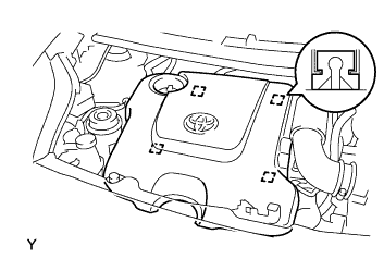 |
Engage the 4 pins and install engine cover No. 1.
| 117. INSTALL ENGINE UNDER COVER |
Provisionally install the engine under cover with the 5 bolts, 4 screws and 2 clips.
Tighten the 4 screws.
Tighten the 5 bolts.
- Torque:
- 5.0 N*m{ 51 kgf*cm , 44 in.*lbf }
| 118. INSTALL FRONT WHEELS |
- Torque:
- 103 N*m{ 1050 kgf*cm , 76 ft.*lbf }
| 119. ADJUST FRONT WHEEL ALIGNMENT |
Click here
Click here
Click here
Click here
Click here
Click here