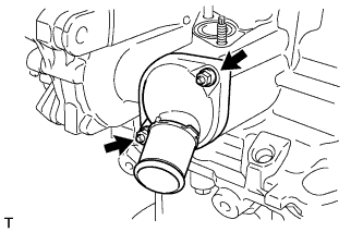
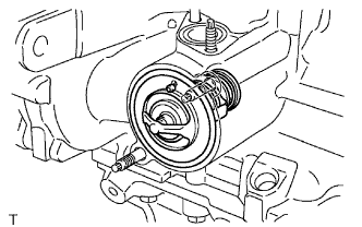
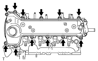
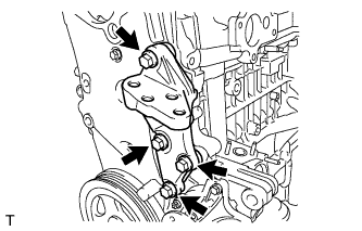
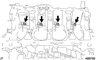
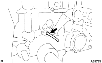
Remove the 4 bolts and nut, then remove the engine mounting bracket.
6.
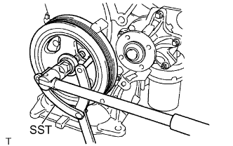
REMOVE CRANKSHAFT DAMPER SUB-ASSEMBLY
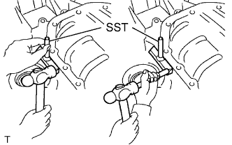
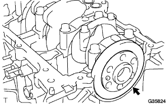
Using SST, hold the crankshaft damper and loosen the crankshaft bolt.
SST
09960-10010
(09962-01000, 09963-01000)
7.
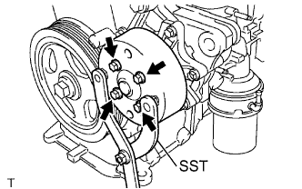
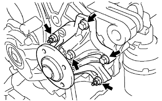
REMOVE WATER PUMP ASSEMBLY
Remove the 3 bolts and 2 nuts, then remove the water pump.
Remove the water pump gasket.
8.
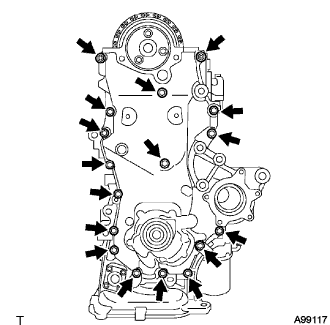
REMOVE OIL PUMP ASSEMBLY
Remove the 16 bolts and the nut.
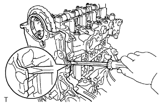
Using a screwdriver with its tip wrapped in protective tape, remove the oil pump by prying between the cylinder head and cylinder block.
NOTICE:
Do not damage the contact surfaces of the oil pump assembly, cylinder head or cylinder block.
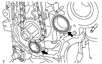
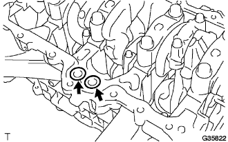
Remove the 2 O-rings from the cylinder block and oil pan.
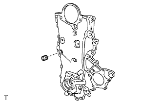
Using an 8 mm socket hexagon wrench, remove the service hole screw plug.
9.
REMOVE OIL PUMP SEAL
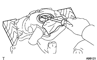
Using a screwdriver with its tip wrapped in protective tape, remove the oil pump seal.
10.
REMOVE CHAIN TENSIONER ASSEMBLY NO. 1
NOTICE:
Do not rotate the crankshaft with the chain tensioner removed.
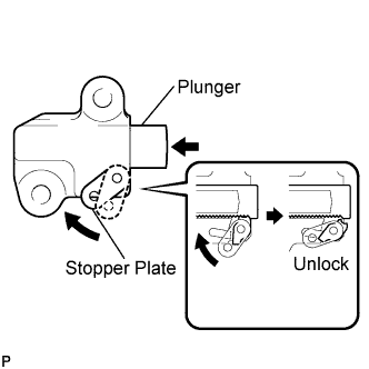
Pull up the stopper plate to unlock the plunger.
Unlock the plunger and push it in to the end.
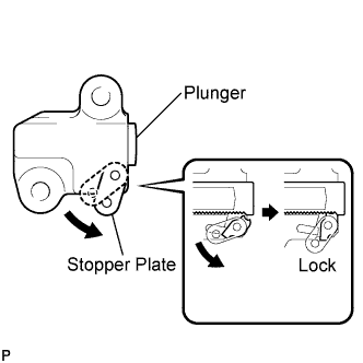
Pull down the stopper plate with the plunger pushed to the end to lock the plunger.
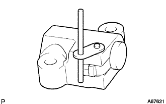
Insert a 2.5 mm (0.098 in.) diameter bar into the hole in the stopper plate with the plunger locked.
HINT:
If the stopper plate is not completely pulled down and a 2.5 mm (0.098 in.) diameter bar cannot be inserted, unlock and pull out the plunger slightly. The stopper plate will be completely pulled down and a 2.5 mm (0.098 in.) diameter bar can be inserted easily.
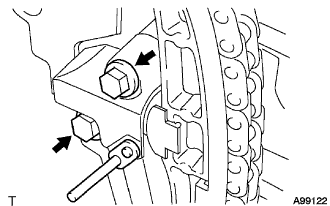
Remove the 2 bolts and chain tensioner No. 1.
11.
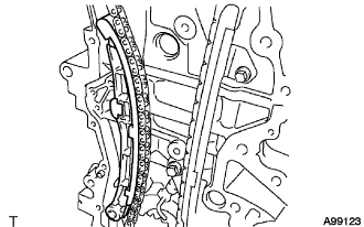
REMOVE CHAIN TENSIONER SLIPPER
Remove the 2 bolts and chain tensioner No. 1.
12.
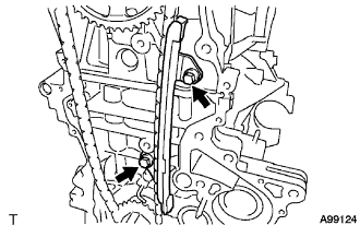
REMOVE CHAIN VIBRATION DAMPER NO. 1
Remove the 2 bolts and chain vibration damper.
13.
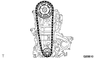
REMOVE CHAIN SUB-ASSEMBLY
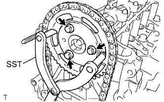
Using SST, hold the camshaft timing sprocket.
SST
09960-10010
(09962-01000, 09963-01000)
Remove the 3 bolts, then remove the camshaft timing sprocket.
Remove the camshaft timing sprocket, crankshaft timing sprocket and chain together.
14.
REMOVE CAMSHAFT
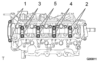
Remove the 10 bolts from the camshaft bearing caps by loosening them in the sequence shown in the illustration, and then remove the 5 camshaft bearing caps.
Remove the camshaft.
NOTICE:
Using several steps, uniformly loosen the bolts while keeping the camshaft level.
Do not remove camshaft bearing cap No. 3.
15.
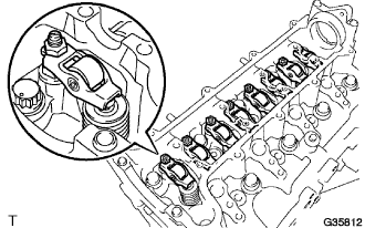
REMOVE VALVE ROCKER ARM SUB ASSEMBLY NO. 1
Remove the valve rocker arm from the cylinder head.
16.
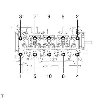
REMOVE CYLINDER HEAD SUB-ASSEMBLY
Using several steps, loosen the 10 bolts in the sequence shown in the illustration, and then remove the bolts and washers.
NOTICE:
When removing the bolts, do not drop the washers into the engine.
Removing the cylinder head bolts in the wrong order may cause damage to the cylinder head.
17.
REMOVE CYLINDER HEAD GASKET
18.
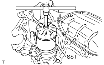
REMOVE OIL FILTER SUB-ASSEMBLY
Using SST, remove the oil filter.
SST
09228-07501
19.
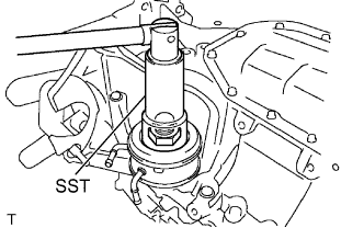
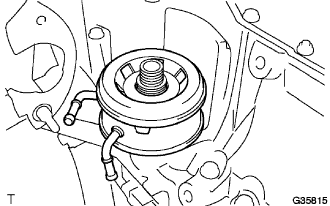
REMOVE OIL COOLER ASSEMBLY
Using SST, remove the nut.
SST
09229-55010
Remove the oil cooler.
20.
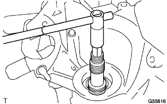
REMOVE OIL FILTER UNION
Using a 12 mm socket hexagon wrench, remove the oil filter union.
21.
REMOVE OIL PAN SUB-ASSEMBLY NO. 2
Remove the oil pan drain plug and gasket.
Remove the 9 bolts and 2 nuts.
Insert the SST blade between the oil pan and oil pan No. 2, and cut off the applied sealer. Remove oil pan No. 2.
SST
09032-00100
NOTICE:
Do not damage the oil pan or oil pan No. 2.
22.
REMOVE OIL STRAINER SUB-ASSEMBLY
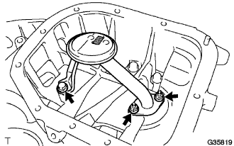
Remove the bolt and 2 nuts, then remove the oil strainer and gasket.
23.
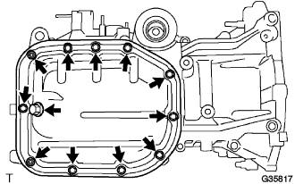
REMOVE OIL PAN SUB-ASSEMBLY
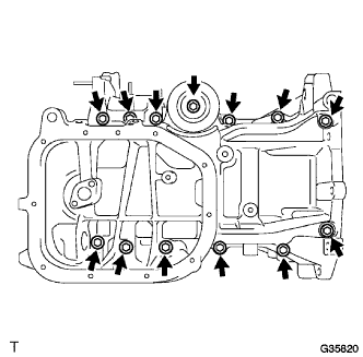
Remove the 13 bolts.
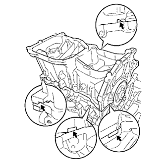
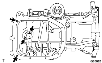
Using screwdriver with its tip wrapped in protective tape, remove the oil pan by prying between the cylinder block and oil pan as illustrated.
NOTICE:
Do not apply excessive force when prying between the cylinder block and oil pan.
Remove the 2 O-rings from the cylinder block.
Using "Torx" socket wrench E5, remove the 4 stud bolts.
24.
REMOVE ENGINE REAR OIL SEAL
Remove the engine rear oil seal.
25.
REMOVE PISTON SUB-ASSEMBLY WITH CONNECTING ROD
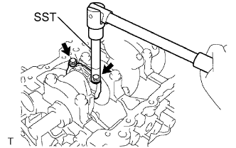
Using SST, remove the bolts and connecting rod caps.
SST
09205-16010
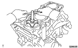
Using a ride reamer, remove all the carbon from the top of the cylinder.
Push the piston, connecting rod and upper bearing through the top of the cylinder block.
HINT:
Keep the bearing, connecting rod and cap together.
Keep the pistons and connecting rods in the correct order so that they can be returned to their original locations when reassembling.
26.
REMOVE CONNECTING ROD BEARING
Remove the connecting rod bearing from the connecting rod cap.
Remove the connecting rod bearing from the connecting rod.
27.
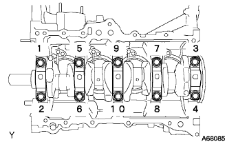
REMOVE CRANKSHAFT
Uniformly loosen the bearing cap bolts in several steps in the sequence and remove them.
Remove the bearing caps and crankshaft.
28.
REMOVE CRANKSHAFT THRUST WASHER UPPER
Remove the crankshaft thrust washer upper from the cylinder block.
29.
REMOVE CRANKSHAFT BEARING
Remove the crankshaft thrust washer upper from the cylinder block.
Remove the crankshaft bearing from the bearing cap.
30.
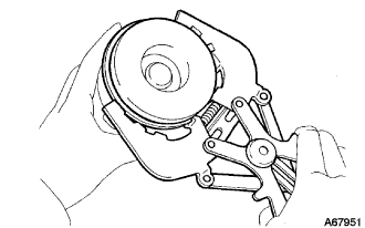
REMOVE PISTON RING SET
HINT:
Keep the piston rings in the correct combination and order so that they can be returned to their original locations when reassembled.
Using a piston ring expander, remove compression rings No. 1 and No. 2 and the oil ring.
31.
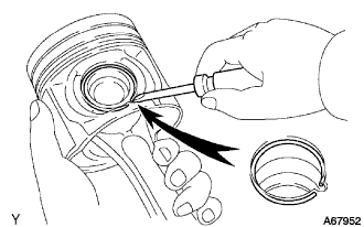
REMOVE WITH PIN PISTON SUB-ASSEMBLY
Using a screwdriver, pry out the snap ring and remove the piston pin.
NOTICE:
Do not alter the combinations of the pistons and piston pins.
32.
REMOVE OIL NOZZLE SUB-ASSEMBLY NO. 1
Using a 5 mm hexagon wrench, remove the 4 bolts and the 4 oil nozzles.
33.
REMOVE OIL JET
Remove the oil jet from the cylinder block.
34.
REMOVE STUD BOLT
Remove the 9 stud bolts indicated in the illustration from the cylinder block.
35.
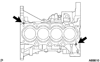
REMOVE CYLINDER HEAD SET STRAIGHT PIN
Remove the 2 cylinder head straight pins indicated in the illustration from the cylinder block.
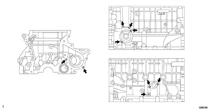
36.
REMOVE OIL PUMP SET RING PIN
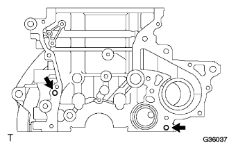
Remove the 2 oil pump ring pins indicated in the illustration from the cylinder block.
37.
REMOVE OIL PUMP SET STRAIGHT PIN
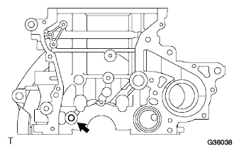
Remove the oil pump straight pin indicated in the illustration from the cylinder block.
38.
REMOVE END PLATE STRAIGHT PIN
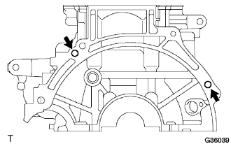
Remove the 2 end plate straight pins indicated in the illustration from the cylinder block.
39.
REMOVE OIL PAN STRAIGHT PIN
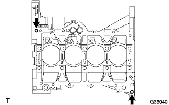
Remove the 2 oil pan straight pins indicated in the illustration from the cylinder block.