REMOVAL
Removal / installation · Vehicles built from Nov 2005
| 1. DRAIN ENGINE COOLANT |

- CAUTION:
- To avoid the danger of being burned, do not remove the radiator cap while the engine and radiator are still hot. Thermal expansion will cause hot engine coolant and steam to blow out from the radiator.
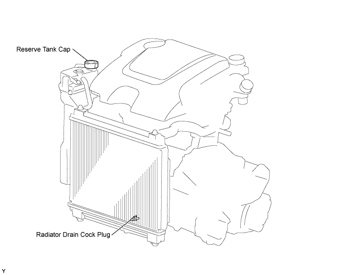
Loosen the radiator drain cock plug.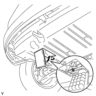

Remove the reserve tank cap and drain the coolant.
Tighten the radiator drain cock plug.
| 2. REMOVE BATTERY |
| 3. REMOVE AIR CLEANER CAP SUB-ASSEMBLY WITH HOSE |
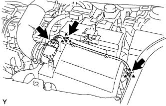 |
Disconnect the mass air flow meter connector.
Disengage the 2 wire harness clamps, and separate the wire harness from the air cleaner cap.
Unfasten the 2 lock clamps, and separate the air cleaner cap.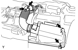
Disconnect the ventilation hose from the cylinder head cover.
Disconnect the air cleaner hose from the turbocharger, and remove the air cleaner with hose.
| 4. REMOVE ENGINE COVER SUB-ASSEMBLY NO. 1 |
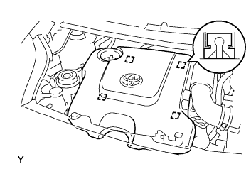 |
Disengage the 4 pins and remove engine cover No. 1.
| 5. REMOVE EGR COOLER ASSEMBLY |
Disconnect the 2 water by-pass hoses.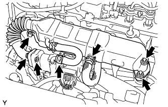
Remove the bolt and 4 nuts, then remove the EGR cooler assembly.
Remove the 2 gaskets.
| 6. REMOVE VACUUM REGULATING VALVE ASSEMBLY |
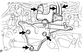 |
Disconnect the connector clamp and connector.
Disengage the 2 hose clamps and disconnect the 2 vacuum hoses.
Remove the 3 bolts, then remove the vacuum regulating valve together with the bracket.
| 7. REMOVE INJECTION PIPE CLAMP NO.1 |
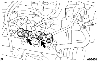 |
Remove the 2 nuts, then remove injection pipe clamp No. 1.
| 8. REMOVE NOZZLE LEAKAGE PIPE ASSEMBLY |
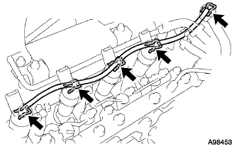 |
Remove the 5 retainer springs, then remove the nozzle leakage pipe.
| 9. REMOVE FUEL INLET PIPE SUB-ASSEMBLY |
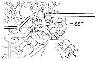 |
Using a spanner (17 mm), hold the supply pump steady, and using SST, remove the fuel inlet pipe from the supply pump side.
- SST
- 09023-38401
Using SST, remove the fuel inlet pipe from the common rail side.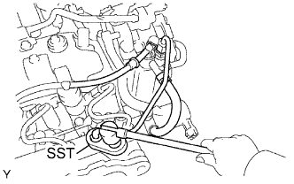
- SST
- 09023-38401
After removing the fuel inlet pipe, cover the common rail with vinyl tape and cover the injector inlet with a vinyl or plastic bag in order to prevent dust and foreign matter from entering.
| 10. REMOVE INJECTION OR SUPPLY PUMP ASSEMBLY |
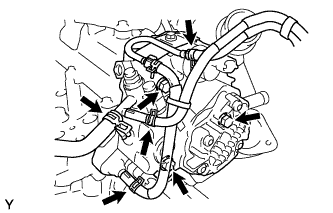 |
Disconnect the 3 fuel hoses.
Disconnect the 2 connectors.
Remove the 3 bolts, then remove the supply pump.
Remove the supply pump driving coupling.
Remove the O-ring.
- NOTICE:
- When removing the supply pump, make sure that the drive coupling does not fall off, as it can be easily removed. If the drive coupling falls off, replace it with a new one.