Pattern Select Switch Circuit
Circuit diagnosis · Vehicles built from Nov 2005
DESCRIPTION
While the vehicle is driven with the shift lever in the E position, the most appropriate gear is automatically selected in accordance with the accelerator pedal opening angle and vehicle speed. In this time, shift control can be switched between normal mode (E) and sports mode (Es) by pressing the pattern select switch.WIRING DIAGRAM
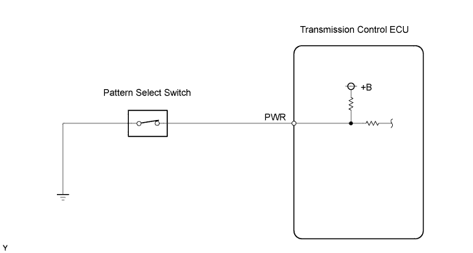

INSPECTION PROCEDURE
| 1. INSPECT PATTERN SELECT SWITCH ASSEMBLY |

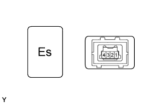 |
Remove the pattern select switch.
Check the resistance of the pattern select switch terminals.
- Standard resistance:
Tester Connections
Switch Conditions
Specified Conditions
1 - 4
ON
Below 1 Ω
1 - 4
OFF
10 kΩ or higher
Reinstall the pattern select switch.
|
|
||||

| OK | |
 |
| 2. CHECK HARNESS AND CONNECTOR (TRANSMISSION CONTROL ECU - BODY GROUND) |
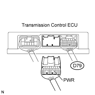 |
Disconnect the transmission control ECU connector.
Check the resistance.
- Standard resistance:
Tester Connections
Switch Conditions
Specified Conditions
PWR (D79-23) - Body ground
OFF
10 kΩ or higher
PWR (D79-23) - Body ground
ON
Below 1 Ω
Reconnect the transmission control ECU connector.
|
|
||||
| OK | |
|
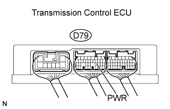
| 3. INSPECT TRANSMISSION CONTROL ECU ASSEMBLY (PWR TERMINAL VOLTAGE) |
 |
Turn the ignition switch on (IG).
Measure the voltage between the terminal of the transmission control ECU connector and the body ground when the pattern select switch is ON and OFF.
- Standard voltage:
Tester Connections
Switch Conditions
Specified Conditions
PWR (D79-23) - Body ground
Pattern select switch OFF
10 to 14 V
PWR (D79-23) - Body ground
Pattern select switch ON
Below 1 V
|
|
||||
| OK | ||
 |
||
| ||