REASSEMBLY
Removal / installation · Vehicles built from Nov 2005
| 1. INSTALL OUTPUT SHAFT COVER |

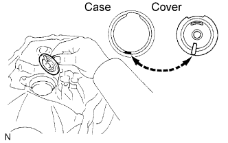  |
Coat the output shaft cover with MP grease and install it onto the front transaxle case.
- NOTICE:
- Fit the output shaft cover projection into the case side hollow.
| 2. INSTALL OUTPUT SHAFT FRONT BEARING |
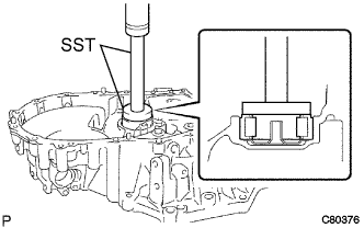 |
Coat a new output shaft front bearing with gear oil, and install it using SST and a press.
- SST
- 09950-60010
(09951-00550)
09950-70010 (09951-07150)
- NOTICE:
- Be sure to install a new bearing in the correct direction, as shown in the illustration.
| 3. INSTALL FRONT TRANSAXLE CASE OIL SEAL |
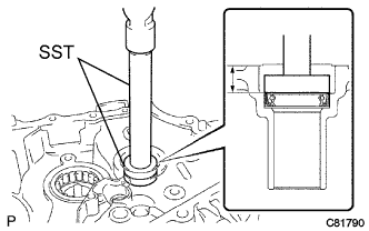 |
Using SST and a hammer, install a new front transaxle case oil seal onto the front transaxle case.
- SST
- 09950-60010
(09951-00370)
09950-70010 (09951-07150)
- Drive in depth:
- 15.6 to 16.0 mm (0.6142 to 0.6299 in.)
Coat the lip of the front transaxle case oil seal with MP grease.
| 4. INSTALL INPUT SHAFT FRONT BEARING |
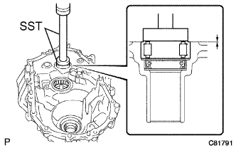 |
Coat a new input shaft front bearing with gear oil.
Using SST and a press, install it onto the front transaxle case.
- SST
- 09950-60010
(09951-00420)
09950-70010 (09951-07150)
- Drive in depth:
- 0 to 0.3 mm (0 to 0.0118 in.)
| 5. INSTALL FRONT DIFFERENTIAL CASE FRONT TAPERED ROLLER BEARING |
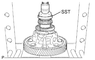 |
Using SST and a press, install the front differential case front tapered roller bearing (inner race) onto the front differential case.
- SST
- 09350-32014
(09351-32120)
09950-60010 (09951-00530)
Using SST and a press, install the front differential case front tapered roller bearing (outer race) with the plate washer onto the front transaxle case.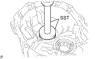
- SST
- 09950-60020
(09951-00680)
09950-70010 (09951-07150)
| 6. INSTALL FRONT DIFFERENTIAL CASE REAR TAPERED ROLLER BEARING |
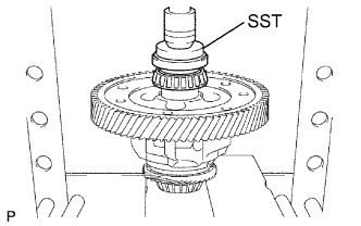 |
Using SST and a press, install the front differential case rear tapered roller bearing (inner race) onto the front differential case.
- SST
- 09350-32014
(09351-32120)
09950-60010 (09951-00530)
Using SST and a press, install the front differential case rear tapered roller bearing (outer race) with the plate washer onto the manual transmission case.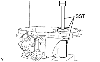
- SST
- 09309-36010
09950-60020 (09951-00710)
09950-70010 (09951-07150)
- HINT:
- Use a front differential case rear plate washer of the same thickness as the removed one.
| 7. ADJUST DIFFERENTIAL SIDE BEARING PRELOAD |
Install the 4 manual transmission case straight pins into the front transaxle case.
Coat the differential case assembly with gear oil, and install it onto the front transaxle case.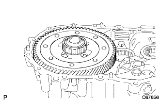
Install the manual transmission case with the 16 bolts.
- Torque:
- 29 N*m{ 300 kgf*cm , 22 ft.*lbf }
Using SST and a torque wrench, turn the differential case assembly to the right and left 2 or 3 times to allow the bearings to settle.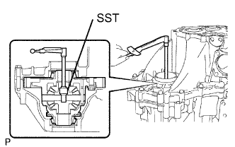
- SST
- 09564-32011
Using SST and a torque wrench, measure the preload.
- SST
- 09564-32011
- Preload (at starting):
- New bearing:
- 0.78 to 1.57 N*m (7.95 to 16.0 kgf*cm, 6.90 to 13.90 in.*lbf)
- Used bearing:
- 0.49 to 0.98 N*m (5.0 to 10.0 kgf*cm, 4.34 to 8.67 in.*lbf)
Select another plate washer.
Mark
Thickness mm (in.)
Mark
Thickness mm (in.)
AA
2.10 (0.0827)
LL
2.60 (0.1024)
BB
2.15 (0.0846)
MM
2.65 (0.1043)
CC
2.20 (0.0866)
NN
2.70 (0.1063)
DD
2.25 (0.0886)
PP
2.75 (0.1083)
EE
2.30 (0.0906)
QQ
2.80 (0.1102)
FF
2.35 (0.0925)
RR
2.85 (0.1122)
GG
2.40 (0.0945)
SS
2.90 (0.1142)
HH
2.45 (0.0965)
TT
2.95 (0.1161)
JJ
2.50 (0.0984)
UU
3.00 (0.1181)
KK
2.55 (0.1004)
-
-
- HINT:
- Select a thicker plate washer to increase the preload or a thinner plate washer to decrease the preload.
Remove the 16 bolts and manual transmission case from the transaxle case.
Remove the differential case assembly from the front transaxle case.
| 8. INSTALL TRANSMISSION CASE OIL SEAL |
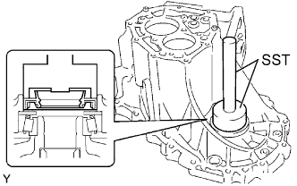 |
Using SST and a hammer, install a new transmission case oil seal onto the manual transmission case.
- SST
- 09726-36010
09950-70010 (09951-07150)
- Drive in depth:
- 9.6 to 10.2 mm (0.3780 to 0.4016 in.)
Coat the lip of the front transmission case oil seal with MP grease.
| 9. INSTALL TRANSAXLE CASE OIL SEAL |
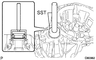 |
Using SST and a hammer, install a new transaxle case oil seal onto the front transaxle case.
- SST
- 09710-20011
(09710-06071)
09950-70010 (09951-07150)
- Drive in depth:
- 1.6 to 2.2 mm (0.0630 to 0.0866 in.)
Coat the lip of the transaxle case oil seal with MP grease.
| 10. INSTALL TRANSMISSION MAGNET |
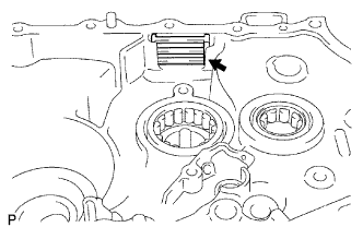 |
Clean the transmission magnet and install it onto the front transaxle case.
| 11. INSTALL BEARING LOCK PLATE |
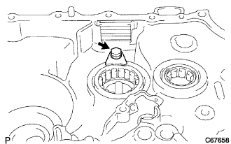 |
Install the bearing lock plate with the bolt.
- Torque:
- 11 N*m{ 115 kgf*cm , 8 ft.*lbf }
| 12. INSTALL OIL RECEIVER PIPE NO. 1 |
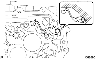 |
Install oil receiver pipe No. 1 onto the manual transmission case with the bolt.
- Torque:
- 17 N*m{ 175 kgf*cm , 13 ft.*lbf }
- NOTICE:
- Be careful not to damage oil receiver pipe No. 1.
- Prevent oil receiver pipe No. 1 from being deformed.
- Install oil receiver pipe No. 1 while placing it against the manual transmission case, as shown in the illustration.
- Be careful not to damage oil receiver pipe No. 1.
| 13. INSTALL OIL RECEIVER PIPE NO. 2 |
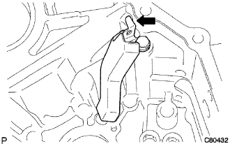 |
Install oil receiver pipe No. 2 onto the manual transmission case with the bolt.
- Torque:
- 17 N*m{ 175 kgf*cm , 13 ft.*lbf }
- NOTICE:
- Be careful not to damage oil receiver pipe No. 2.
- Prevent oil receiver pipe No. 2 from being deformed.
- Install oil receiver pipe No. 2 while placing it against the manual transmission case, as shown in the illustration.
- Be careful not to damage oil receiver pipe No. 2.
| 14. INSTALL REVERSE RESTRICT PIN ASSEMBLY |
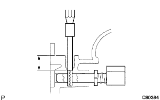 |
Install the reverse restrict pin into the manual transmission case.
- HINT:
- Orient the reverse restrict pin correctly.
Using a pin punch (φ 5 mm) and a hammer, install the slotted pin into the reverse restrict pin.
- Drive in depth:
- 15.5 to 16.5 mm (0.6102 to 0.6496 in.)
Apply sealant to the reverse restrict pin plug.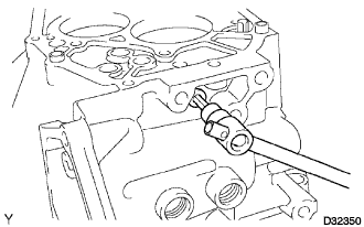
- Sealant:
- Toyota Genuine Adhesive 1344, Three Bond 1344 or Equivalent
Using a hexagon wrench and a torque wrench, install the reverse restrict pin plug into the manual transmission case.
- Torque:
- 13 N*m{ 129 kgf*cm , 9 ft.*lbf }
| 15. INSTALL MANUAL TRANSAXLE CASE RECEIVER |
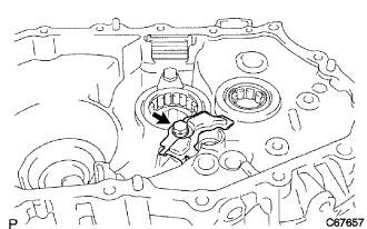 |
Install the manual transaxle case receiver onto the front transaxle case with the bolt.
- Torque:
- 11 N*m{ 115 kgf*cm , 8 ft.*lbf }
| 16. INSTALL DIFFERENTIAL CASE ASSEMBLY |
|
|
Coat the differential case tapered roller bearing with gear oil, and install it onto the front transaxle case.
| 17. INSTALL INPUT SHAFT ASSEMBLY |
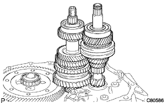 |
Coat the sliding and rotating surfaces of the input and output shafts with gear oil, and install them onto the front transaxle case.
| 18. INSTALL REVERSE IDLER GEAR SUB-ASSEMBLY |
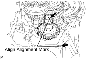 |
Coat the reverse idler gear, thrust washer and reverse idler gear shaft with gear oil, and install them.
- HINT:
- Align the mark on the reverse idler gear shaft with the bolt hole as shown in the illustration.
| 19. INSTALL GEAR SHIFT FORK SHAFT NO. 1 |
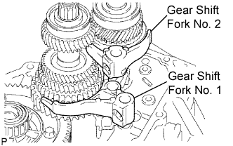 |
Coat gear shift fork No. 1 and gear shift fork No. 2 with gear oil, and install them.
Coat gear shift fork No. 1 with gear oil, and install it.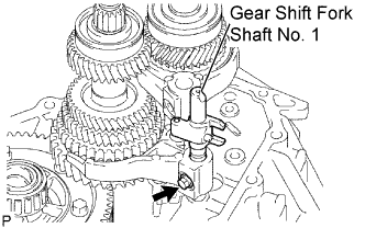
Apply sealant to the shift fork set bolt.
- Sealant:
- Toyota Genuine Adhesive 1344, Three Bond 1344 or Equivalent
Install the gear shift fork set bolt.
- Torque:
- 16 N*m{ 160 kgf*cm , 12 ft.*lbf }
Using a brass bar and a hammer, install a shift head snap ring onto gear shift fork shaft No. 1.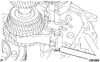
| 20. INSTALL GEAR SHIFT FORK SHAFT NO. 3 |
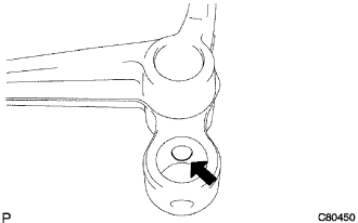 |
Coat the 2 shift fork balls with MP grease, and install them into the reverse shift fork.
Install the reverse shift fork onto gear shift fork shaft No. 3.
Using a brass bar and a hammer, install 2 new shift fork shaft snap rings onto shift fork shaft No. 3.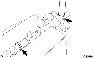
Coat shift fork shaft No. 3 with gear oil, and install it.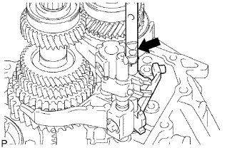
| 21. INSTALL GEAR SHIFT FORK SHAFT NO. 2 |
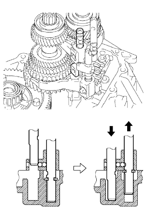 |
Coat gear shift head No. 1 and gear shift fork shaft No. 2 with gear oil, and install them.
- NOTICE:
- To avoid interference from the 2 shift fork balls, lift up the gear shift fork shaft No. 3 as shown in the illustration.
Coat the 2 shift fork set bolts with sealant, and install them onto gear shift fork No. 2 and shift head No. 1.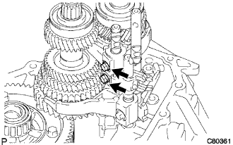
- Torque:
- 16 N*m{ 160 kgf*cm , 12 ft.*lbf }
- Sealant:
- Toyota Genuine Adhesive 1344, Three Bond 1344 or Equivalent
| 22. INSTALL REVERSE SHIFT ARM BRACKET ASSEMBLY |
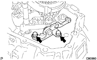 |
Install the reverse shift arm bracket onto the front transaxle case with the 2 bolts .
- Torque:
- 17 N*m{ 175 kgf*cm , 13 ft.*lbf }
| 23. INSTALL MANUAL TRANSMISSION CASE |
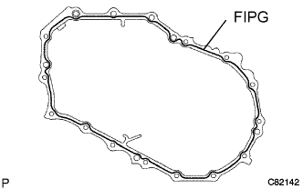 |
Apply FIPG to the manual transmission case, as shown in the illustration.
- FIPG:
- Toyota Genuine Seal Packing 1281, Three Bond 1281 or Equivalent
- NOTICE:
- Parts must be assembled within 10 minutes of the application. Otherwise, the packing (FIPG) material must be removed and reapplied.
Coat the 13 bolts with sealant, and install the manual transmission case with the 13 bolts.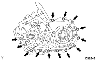
- Torque:
- 29 N*m{ 300 kgf*cm , 22 ft.*lbf }
- Sealant:
- Toyota Genuine Adhesive 1344, Three Bond 1344 or Equivalent
Coat the 3 bolts with sealant, and install the front transaxle case with the 3 bolts.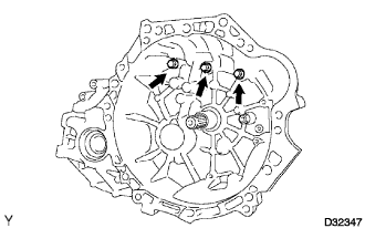
- Torque:
- 29 N*m{ 300 kgf*cm , 22 ft.*lbf }
- Sealant:
- Toyota Genuine Adhesive 1344, Three Bond 1344 or Equivalent
| 24. INSTALL REVERSE IDLER GEAR SHAFT BOLT |
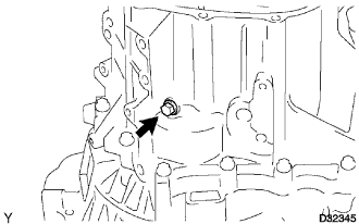 |
Coat the reverse idler gear shaft bolt with sealant, and install a new gasket with the bolt.
- Torque:
- 29 N*m{ 300 kgf*cm , 22 ft.*lbf }
- Sealant:
- Toyota Genuine Adhesive 1344, Three Bond 1344 or Equivalent
| 25. INSTALL LOCK BALL ASSEMBLY NO. 2 |
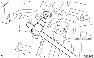 |
Coat lock ball No. 2 with sealant, and install it using a hexagon wrench.
- Torque:
- 29 N*m{ 296 kgf*cm , 21 ft.*lbf }
- Sealant:
- Toyota Genuine Adhesive 1344, Three Bond 1344 or Equivalent
| 26. INSTALL SHIFT DETENTE BALL PLUG |
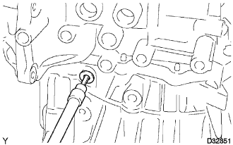 |
Coat the shift detente ball plug with sealant, and install it using a hexagon wrench.
- Torque:
- 22 N*m{ 224 kgf*cm , 16 ft.*lbf }
- Sealant:
- Toyota Genuine Adhesive 1344, Three Bond 1344 or Equivalent
| 27. INSTALL INPUT SHAFT REAR BEARING HOLE SNAP RING |
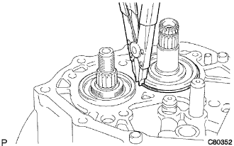 |
Using a snap ring expander, install a new input shaft rear bearing hole snap ring onto the input shaft.
| 28. INSTALL OUTPUT SHAFT REAR BEARING HOLE SNAP RING |
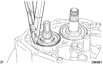 |
Using a snap ring expander, install a new output shaft rear bearing hole snap ring onto the output shaft.
| 29. INSTALL SHIFT FORK SHAFT SHAFT SNAP RING |
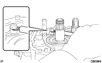 |
Using a brass bar and a hammer, install a new shift fork shaft snap ring onto shift fork shaft No. 2.
| 30. INSTALL BEARING RETAINER REAR |
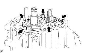 |
Coat the 5 bolts with sealant, and install the bearing retainer rear onto the manual transmission case with the 5 bolts.
- Torque:
- 27 N*m{ 279 kgf*cm , 20 ft.*lbf }
| 31. INSTALL 5TH DRIVEN GEAR |
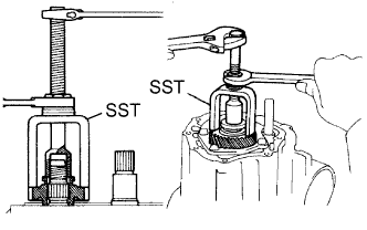 |
Using SST, install the 5th driven gear onto the output shaft.
- SST
- 09309-12020
| 32. INSTALL 5TH GEAR NEEDLE ROLLER BEARING |
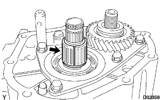 |
Coat the 5th gear needle roller bearing and spacer with gear oil, and install them onto the input shaft.
| 33. INSTALL 5TH GEAR |
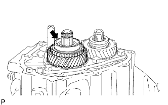 |
Coat the 5th gear with gear oil, and install it onto the input shaft.
| 34. INSTALL SYNCHRONIZER RING NO. 3 |
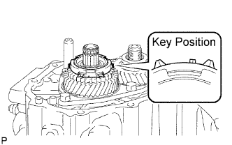 |
Coat synchronizer ring No. 3 with gear oil, and install it onto the 5th gear.
| 35. INSTALL TRANSMISSION CLUTCH HUB NO. 3 |
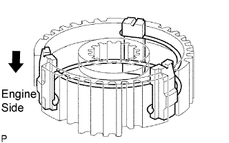 |
Install the 3 synchromesh shifting keys and 2 synchromesh shifting key springs onto transmission clutch hub No. 3.
- NOTICE:
- Do not align the openings of the shifting key springs.
Using SST and a hammer, install transmission clutch hub No. 3 onto the input shaft.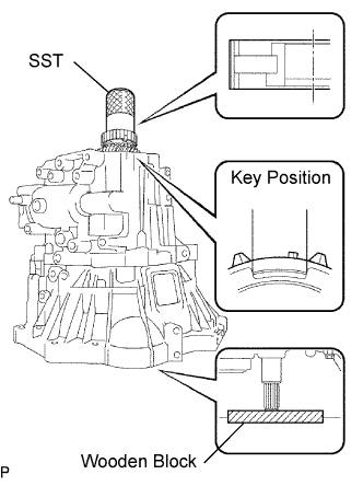
- SST
- 09636-20010
- NOTICE:
- Do not install transmission clutch hub No. 3 with it facing the wrong direction.
- Install transmission clutch hub No. 3 while checking the positions of the synchronizer ring No. 3 key groove and synchromesh shifting key No. 3.
- Check that the 5th gear rotates.
- Place the suitable sized wooden block to support the input shaft.
- Do not install transmission clutch hub No. 3 with it facing the wrong direction.
Select a clutch hub No. 3 shaft snap ring that will allow minimum axial play.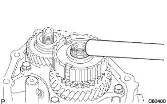
- Clearance:
- 0.1 mm (0.0039 in.) or less
Mark
Thickness mm (in.)
Mark
Thickness mm (in.)
A
2.25 (0.0886)
E
2.49 (0.0980)
B
2.31 (0.0909)
F
2.55 (0.1004)
C
2.37 (0.0933)
G
2.61 (0.1028)
D
2.43 (0.0957)
-
-
Using a brass bar and a hammer, install the new snap ring onto the input shaft.
| 36. INSPECT 5TH GEAR THRUST CLEARANCE |
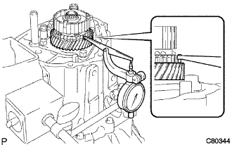 |
Using a dial indicator, measuer the 5th gear thrust clearance.
- Standard clearance:
- 0.10 to 0.57 mm (0.0039 to 0.0224 in.)
- Maximum clearance:
- 0.57 mm (0.0224 in.)
| 37. INSPECT 5TH GEAR RADIAL CLEARANCE |
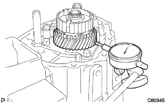 |
Using a dial indicator, measure the 5th gear radial clearance.
- Standard clearance:
- KOYO made:
- 0.015 to 0.058 mm (0.0006 to 0.0023 in.)
- NSK made:
- 0.015 to 0.056 mm (0.0006 to 0.0022 in.)
- Maximum clearance:
- KOYO made:
- 0.058 mm (0.0023 in.)
- NSK made:
- 0.056 mm (0.0022 in.)
| 38. INSTALL GEAR SHIFT FORK NO. 3 |
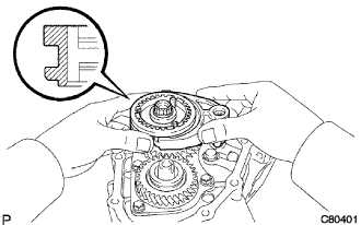 |
Coat transmission clutch hub sleeve No. 3 with gear oil, and install it with the gear shift fork No. 3 onto transmission clutch hub No. 3.
- HINT:
- Orient transmission clutch hub No. 3 correctly.
Coat the gear shift fork set bolt with sealant, and install it onto gear shift fork No. 3.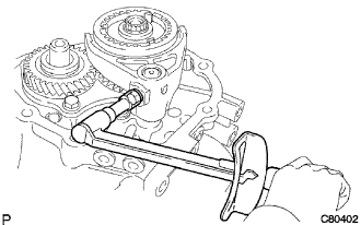
- Torque:
- 16 N*m{ 160 kgf*cm , 12 ft.*lbf }
- Sealant:
- Toyota Genuine Adhesive 1344, Three Bond 1344 or Equivalent
| 39. INSTALL MANUAL TRANSMISSION OUTPUT SHAFT REAR SET NUT |
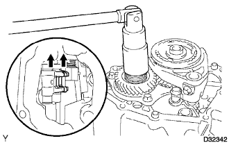 |
Engage the 2 gears simultaneously to lock the transmission.
Install a new manual transmission output shaft rear set nut.
- Torque:
- 118 N*m{ 1,199 kgf*cm , 87 ft.*lbf }
Using a chisel and a hammer, stake the manual transmission output shaft rear set nut.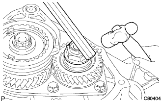
Disengage the gears.
| 40. INSTALL MANUAL TRANSMISSION CASE COVER SUB-ASSEMBLY |
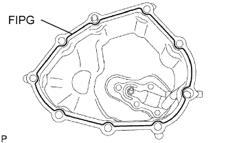 |
Apply FIPG to the transaxle case cover as shown in the illustration.
- FIPG:
- Toyota Genuine Seal Packing 1281, Three Bond 1281 or Equivalent
- NOTICE:
- Parts must be assembled within 10 minutes of the application. Otherwise, the packing (FIPG) material must be removed and reapplied.
Install the manual transmission case cover and 2 wire harness clamps onto the manual transmission case with the 9 bolts.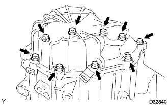
- Torque:
- 14 N*m{ 143 kgf*cm , 10 ft.*lbf }
| 41. INSTALL SHIFT AND SELECT ACTUATOR ASSEMBLY |
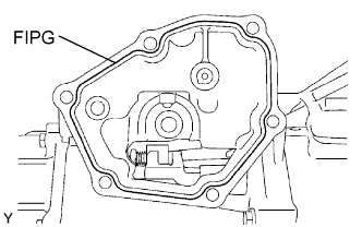 |
Apply FIPG to the manual transmission case as shown in the illustration.
- FIPG:
- Toyota Genuine Seal Packing 1281, Three Bond 1281 or Equivalent
- NOTICE:
- Parts must be assembled within 10 minutes of the application. Otherwise, the packing (FIPG) material must be removed and reapplied.
Install the shift and select actuator onto the manual transmission case with the wire harness clamp bracket and new 6 bolts.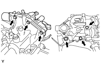
- Torque:
- 18 N*m{ 184 kgf*cm , 13 ft.*lbf }
Install the plug and a new gasket onto the manual transmission case.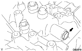
- Torque:
- 39 N*m{ 400 kgf*cm , 29 ft.*lbf }
| 42. INSTALL LOCK BALL ASSEMBLY NO. 1 |
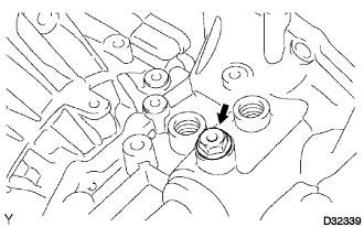 |
Coat lock ball No. 1 with sealant, and install it onto the manual transmission case.
- Torque:
- 37 N*m{ 375 kgf*cm , 27 ft.*lbf }
- Sealant:
- Toyota Genuine Adhesive 1344, Three Bond 1344 or Equivalent
| 43. INSTALL NEUTRAL POSITION SWITCH ASSEMBLY |
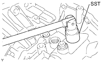 |
Using SST, install the neutral position switch with a new gasket onto the manual transmission case.
- SST
- 09817-16011
- Torque:
- 29 N*m{ 300 kgf*cm , 22 ft.*lbf }
| 44. INSTALL BACK UP LIGHT SWITCH ASSEMBLY |
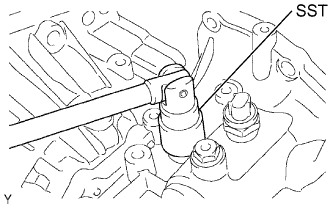 |
Using SST, install the back up light switch with a new gasket onto the manual transmission case.
- SST
- 09817-16011
- Torque:
- 40 N*m{ 410 kgf*cm , 30 ft.*lbf }
| 45. INSTALL TRANSMISSION REVOLUTION SENSOR |
Install a new O-ring onto the transmission revolution sensor.
Install the transmission revolution sensor.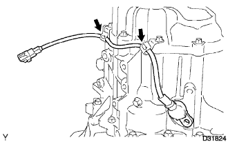
Install the transmission case protector with the 2 bolts.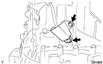
- Torque:
- 8.0 N*m{ 82 kgf*cm , 71 in.*lbf }
| 46. INSTALL SPEEDOMETER DRIVEN HOLE COVER SUB-ASSEMBLY |
Install a new O-ring onto the speedometer driven hole cover.
Install the speedometer driven hole cover onto the front transaxle case with the bolt.
- Torque:
- 11 N*m{ 115 kgf*cm , 8 ft.*lbf }
| 47. INSTALL RELEASE FORK SUPPORT |
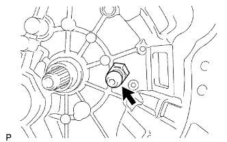 |
Install the release fork support onto the front transaxle case.
- Torque:
- 37 N*m{ 375 kgf*cm , 27 ft.*lbf }
| 48. INSTALL CLUTCH RELEASE FORK SUPPORT BOOT |
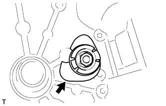 |
Install the clutch release fork support boot to the release fork support as shown in the illustration.
| 49. INSTALL CLUTCH RELEASE FORK BOOT |
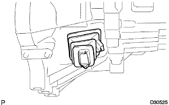 |
Install the clutch release fork boot onto the front transaxle case.
| 50. INSTALL CLUTCH RELEASE BEARING ASSEMBLY |
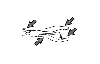 |
Apply release hub grease to the contact surfaces of the release fork and release bearing, release fork and pull rod, and release fork and fork support.
- Sealant:
- Multemp 8158 Grease or Equivalent
Install the release fork onto the release bearing with the clip.
| 51. INSTALL CLUTCH RELEASE FORK SUB-ASSEMBLY |
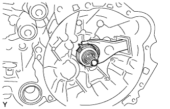 |
Install the clutch release bearing with release fork onto the front transaxle case.
Apply clutch spline grease to the input shaft spline.
- Sealant:
- Toyota Genuine Clutch Spline Grease or Equivalent
| 52. INSTALL MANUAL TRANSMISSION FILLER PLUG |
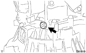 |
Install the manual transmission filler plug with a new gasket onto the manual transmission case.
- Torque:
- 39 N*m{ 400 kgf*cm , 29 ft.*lbf }
| 53. INSTALL DRAIN PLUG SUB-ASSEMBLY |
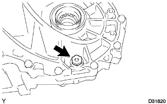 |
Install the drain plug with a new gasket onto the manual transmission case.
- Torque:
- 39 N*m{ 400 kgf*cm , 29 ft.*lbf }