DISASSEMBLY
Removal / installation · Vehicles built from Nov 2005
| 1. REMOVE CAMSHAFT POSITION SENSOR |

Remove the bolt and remove the camshaft position sensor.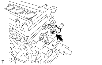

| 2. REMOVE CRANKSHAFT POSITION SENSOR |
Remove the bolt and remove the crankshaft position sensor.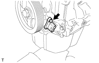
| 3. REMOVE ENGINE OIL PRESSURE SWITCH ASSEMBLY |
for DENSO, YAZAKI made: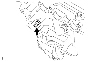
Using a 22 mm (0.8661 in.) deep socket wrench, remove the oil pressure switch.
for JAEGER made:
Using a 24 mm (0.9449 in.) deep socket wrench, remove the oil pressure switch.
| 4. REMOVE OIL FILLER CAP SUB-ASSEMBLY |
Remove the oil filler cap.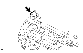
Remove the gasket.
| 5. REMOVE VENTILATION VALVE SUB-ASSEMBLY |
Remove the ventilation valve.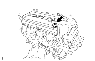
Remove the grommet.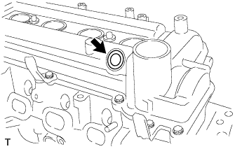
| 6. REMOVE CYLINDER HEAD COVER SUB-ASSEMBLY |
Remove the 11 bolts and 2 nuts and remove the cylinder head cover.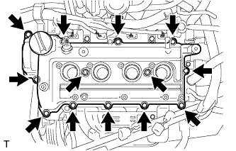
| 7. REMOVE CAM TIMING OIL CONTROL VALVE ASSEMBLY |
Remove the bolt and remove the cam timing oil control valve.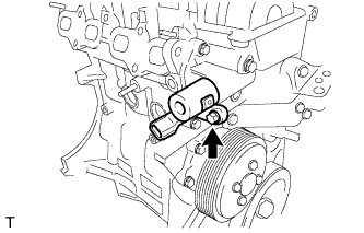
| 8. REMOVE CRANKSHAFT PULLEY |
Turn the crankshaft clockwise and set the No. 1 cylinder to TDC/compression.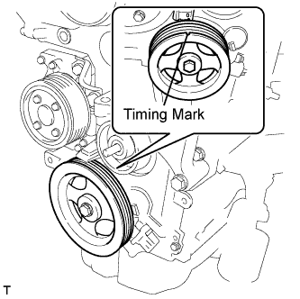
Turn the crankshaft 90° clockwise from TDC/compression.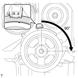
- HINT:
- After separating the chain, set the valve and piston in a position where they do not interfere with each other when the camshaft is turned.
w/o service hole: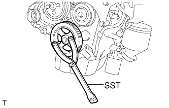
Using SST, hold the crankshaft pulley and loosen the bolt.
- SST
- 09960-10010
(09963-01000, 91651-60855)
w/ service hole: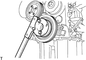
Using SST, hold the crankshaft pulley and loosen the bolt.
- SST
- 09330-00021
09213-54015 (91651-60855)
Remove the bolt and remove the crankshaft pulley.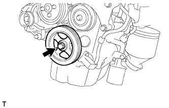
| 9. REMOVE ENGINE MOUNTING STAY RH |
Remove the 2 bolts and remove the engine mounting stay RH.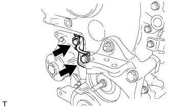
| 10. REMOVE TRANSVERSE ENGINE ENGINE MOUNTING BRACKET |
Remove the 2 bolts and nut and remove the engine mounting bracket.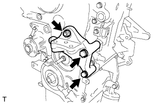
| 11. REMOVE OIL PAN SUB-ASSEMBLY |
Remove the 12 bolts and 2 nuts.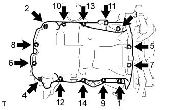
Using a screwdriver with its tip wrapped in protective tape, pry out the oil pan.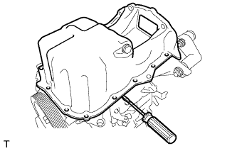
| 12. REMOVE OIL STRAINER SUB-ASSEMBLY |
Remove the bolt and 2 nuts and remove the oil strainer.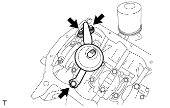
Remove the oil strainer gasket.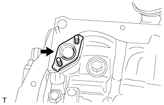
| 13. REMOVE TIMING CHAIN OR BELT COVER SUB-ASSEMBLY |
Remove the 10 bolts and nut.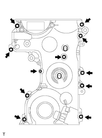
Using a screwdriver with its tip wrapped in protective tape, pry out the timing chain cover.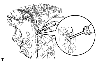
- NOTICE:
- Do not damage the timing chain cover, the cylinder block or the cylinder head.
Remove the gasket.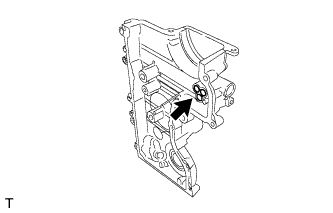
| 14. REMOVE TIMING CHAIN OR BELT COVER OIL SEAL |
Using a screwdriver, remove the oil seal.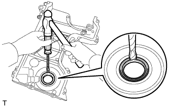
| 15. REMOVE NO. 1 CRANKSHAFT POSITION SENSOR PLATE |
Remove the No. 1 crankshaft position sensor plate.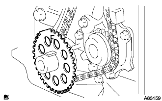
| 16. REMOVE CHAIN TENSIONER PLUNGER |
Move the stopper plate downward and hold it with its lock released.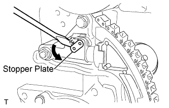
- HINT:
- If the lock of the stopper plate is hard to release, using the hexagonal portion of the camshaft, turn the camshaft slightly left and right.
While holding the stopper plate lowered and the lock released, push the plunger in to the end, and lock it.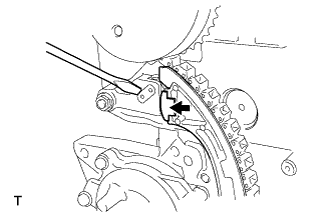
Align the holes in the stopper plate and the chain tensioner plunger.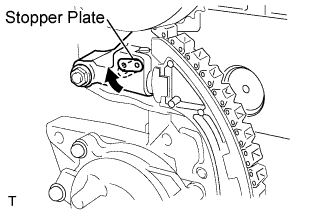
- HINT:
- If it is hard to align the holes in the stopper plate and the chain tensioner plunger, slightly turn the camshaft to both ways and align them.
Insert a 3 mm diameter bar into the holes in the stopper plate and the chain tensioner plunger.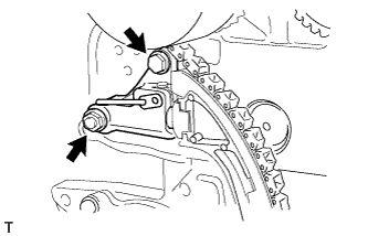
Remove the bolt and the nut and remove the chain tensioner plunger.
| 17. REMOVE TIMING CHAIN TENSION ARM |
Remove the bolt and remove the timing chain tension arm.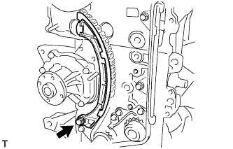
| 18. REMOVE TIMING CHAIN GUIDE |
Remove the 2 bolts and remove the timing chain guide.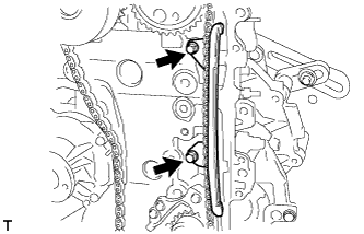
| 19. REMOVE NO. 2 TIMING CHAIN GUIDE |
Remove the 2 bolts and remove the No. 2 timing chain guide.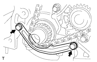
| 20. REMOVE CHAIN SUB-ASSEMBLY |
| 21. REMOVE NO. 1 OIL NOZZLE SUB-ASSEMBLY |
Remove the bolt and remove the No. 1 oil nozzle.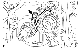
| 22. REMOVE OIL PUMP ASSEMBLY |
Remove the 3 bolts and remove the oil pump.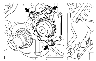
| 23. REMOVE CRANKSHAFT TIMING GEAR OR SPROCKET |
Remove the woodruff key and the crankshaft timing sprocket.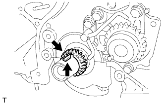
| 24. REMOVE CAMSHAFT TIMING SPROCKET ASSEMBLY |
While holding the hexagonal portion of the camshaft, remove the bolt and the camshaft timing sprocket.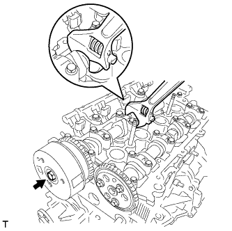
| 25. REMOVE NO. 2 CAMSHAFT |
Remove the 4 bolts and remove the bearing cap.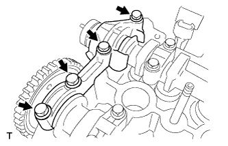
Using the hexagonal head portion of the camshaft, revolve the camshaft so that the cam noses of cylinders No. 2 and No. 4 face as shown in the illustration.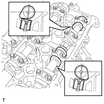
Remove the camshaft bearing caps and bolts in the sequence shown in the illustration.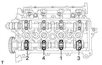
Remove the exhaust camshaft assembly.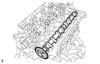
| 26. REMOVE CAMSHAFT |
Using the hexagonal head portion of the camshaft, revolve the camshaft so that the cam noses of cylinders No. 3 and No. 4 face as shown in the illustration.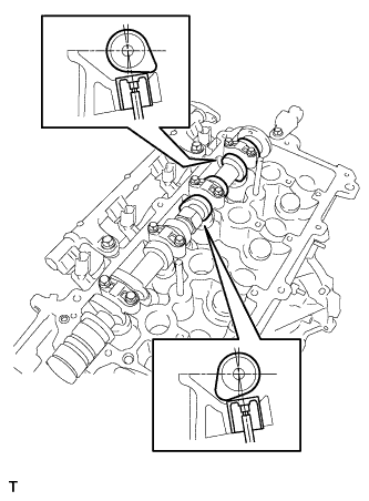
Remove the camshaft bearing caps and bolts in the sequence shown in the illustration.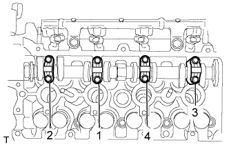
Remove the camshaft.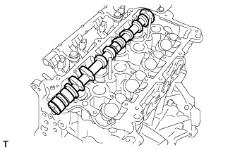
| 27. REMOVE CAMSHAFT TIMING GEAR OR SPROCKET |
Remove the 3 bolts and remove the camshaft timing gear or sprocket.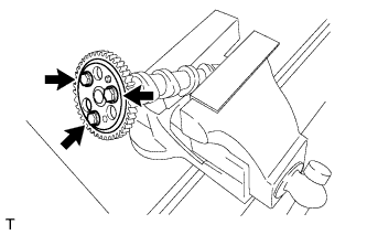
| 28. REMOVE CYLINDER HEAD SUB-ASSEMBLY |
Using several steps, loosen and remove the 10 cylinder head bolts uniformly with an 8 mm bi-hexagon wrench in the sequence shown in the illustration. Remove the plate washers.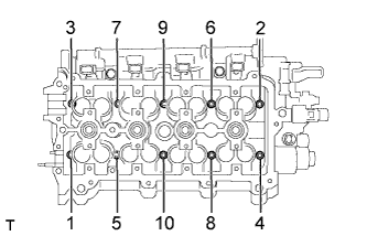
- NOTICE:
- Do not drop the washers into the cylinder head.
- Head warpage or cracking could result from removing the bolts in the wrong order.
- Do not drop the washers into the cylinder head.
| 29. REMOVE CYLINDER HEAD GASKET |
Remove the cylinder head gasket.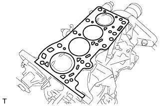
| 30. REMOVE OIL FILTER SUB-ASSEMBLY |
Using SST, remove the oil filter.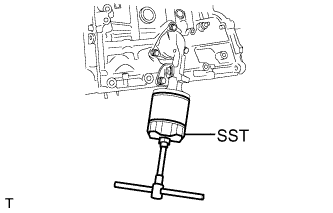
- SST
- 09228-06501
| 31. REMOVE OIL FILTER BRACKET |
Remove the 2 bolts and remove the oil filter bracket.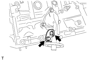
| 32. REMOVE OIL FILTER BRACKET SUB-ASSEMBLY |
Remove the 3 bolts and the oil filter bracket sub-assembly.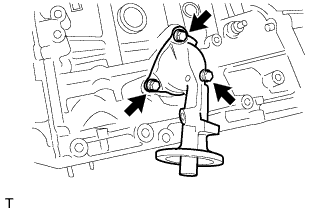
Remove the O-ring.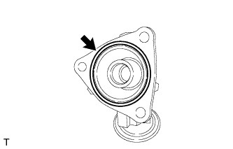
| 33. REMOVE OIL PIPE ASSEMBLY |
Using a 12 mm hexagon wrench, remove the oil pipe assembly.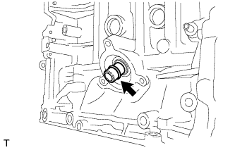
Remove the O-ring.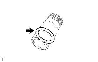
| 34. REMOVE ENGINE REAR OIL SEAL RETAINER |
Remove the 4 bolts.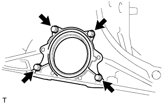
Using a screwdriver with its tip wrapped in protective tape, pry out the oil seal retainer.
| 35. REMOVE ENGINE REAR OIL SEAL |
Using a screwdriver with its tip wrapped in protective tape, remove the oil seal.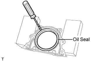
| 36. INSPECT CONNECTING ROD THRUST CLEARANCE |
Using a dial indicator, measure the thrust clearance while moving the connecting rod back and forth.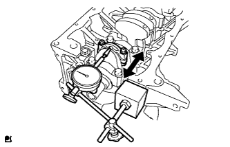
- Standard thrust clearance:
- 0.1 to 0.3 mm (0.004 to 0.012 in.)
- Maximum thrust clearance:
- 0.35 mm (0.0138 in.)
| 37. INSPECT CONNECTING ROD OIL CLEARANCE |
Check that the matchmarks on the connecting rod and connecting rod cap are aligned to ensure correct reassembly.
Using SST, remove the 2 connecting rod cap bolts and connecting rod cap.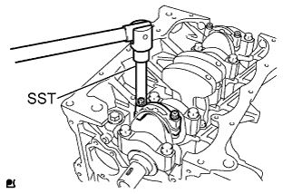
- SST
- 09205-16010
Clean the crank pin and bearing.
Check the crank pin and bearing for pitting and scratches.
Lay a strip of plastigage across the crank pin.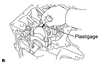
- NOTICE:
- Do not turn the crankshaft.
Make sure that the connecting rod and its connecting rod cap are in the correct combination and that the front mark of the cap is facing in the correct mounting orientation, then install the cap onto the connecting rod.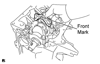
Apply a light coat of engine oil to the threads of the connecting rod cap bolts.
Using SST, tighten the bolts in several steps to the specified torque.
- SST
- 09205-16010
- Torque:
- 22 N*m{ 224 kgf*cm , 16 ft.*lbf }
Mark the front of the connecting cap bolts with paint.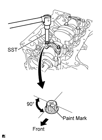
Retighten the connecting rod cap bolts by 90° as shown in the illustration.
Using SST, remove the 2 connecting rod cap bolts and connecting rod cap.
- SST
- 09205-16010
Measure the plastigage at its widest point.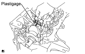
- Standard oil clearance:
- Standard bearing:
- 0.016 to 0.040 mm (0.00063 to 0.00157 in.)
- U/S (0.25) bearing:
- 0.017 to 0.047 mm (0.00067 to 0.00185 in.)
- Maximum oil clearance:
- 0.04 mm (0.0016 in.)
- NOTICE:
- Completely remove the plastigage after the measurement.
When replacing a bearing, replace it with one with the same number as marked on the connecting rod. There are 3 sizes of standard bearings, marked 1, 2 and 3 accordingly.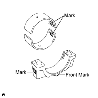
- Standard bearing center wall thickness:
Mark
mm (in.)
1
1.488 to 1.492 (0.05858 to 0.05874)
2
1.492 to 1.496 (0.05874 to 0.05890)
3
1.496 to 1.500 (0.05890 to 0.05906)
| 38. REMOVE WITH PIN PISTON SUB-ASSEMBLY |
Using a ridge reamer, remove all the carbon from the top of the cylinder.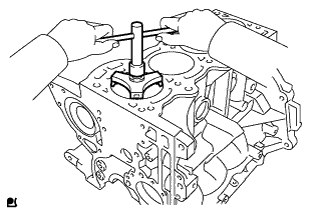
Using SST, remove the 2 connecting rod cap bolts and connecting rod cap.
- SST
- 09205-16010
Push the piston sub-assembly, connecting rod sub-assembly and connecting rod bearing upper through the top of the cylinder block to remove them.
- HINT:
- Keep the piston sub-assembly, connecting rod sub-assembly and connecting rod cap together.
- Keep the piston sub-assembly, connecting rod sub-assembly, and connecting rod cap in the correct order so that they can be returned to their original locations when reassembled.
- Keep the piston sub-assembly, connecting rod sub-assembly and connecting rod cap together.
| 39. REMOVE CONNECTING ROD BEARING SET |
Remove the connecting rod bearing upper.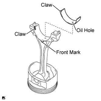
- HINT:
- Keep the connecting rod sub-assemblies and connecting rod bearings together.
- Keep the connecting rod sub-assemblies and connecting rod bearings in the correct order so that they can be returned to their original locations when reassembled.
- Keep the connecting rod sub-assemblies and connecting rod bearings together.
Remove the connecting rod bearing lower.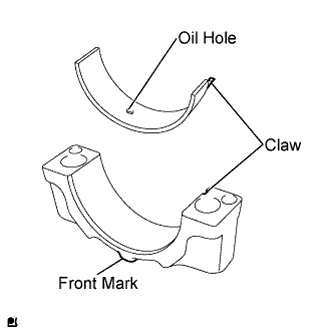
- HINT:
- Keep the connecting rod caps and connecting rod bearings together.
- Keep the connecting rod caps and connecting rod bearings in the correct order so that they can be returned to their original locations when reassembled.
- Keep the connecting rod caps and connecting rod bearings together.
| 40. INSPECT CRANKSHAFT THRUST CLEARANCE |
Using a dial indicator, measure the thrust clearance while moving the crankshaft back and forth with a screwdriver.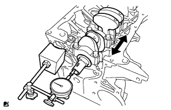
- Standard thrust clearance:
- 0.020 to 0.220 mm (0.00079 to 0.00866 in.)
- Maximum thrust clearance:
- 0.30 mm (0.0118 in.)
- Thrust washer thickness:
Type
mm (in.)
STD
1.940 to 1.990 (0.07638 to 0.07825)
O/S (0.125)
2.062 to 2.115 (0.08130 to 0.08327)
O/S (0.250)
2.190 to 2.240 (0.08622 to 0.08819)
| 41. INSPECT CRANKSHAFT OIL CLEARANCE |
Using several steps, loosen and remove the 10 crankshaft bearing cap set bolts uniformly in the sequence shown in the illustration.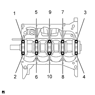
Remove the crankshaft bearing cap.
Clean each main journal and bearing.
Lay a strip of Plastigage across each journal.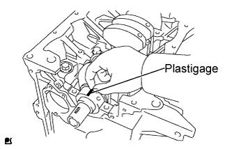
- NOTICE:
- Do not turn the crankshaft.
Examine the front marks and numbers and install the bearing cap onto the cylinder block.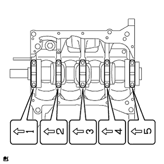
Apply a light coat of engine oil to the threads of the bearing cap bolts.
Install and uniformly tighten the bolts, in several steps, in the sequence shown.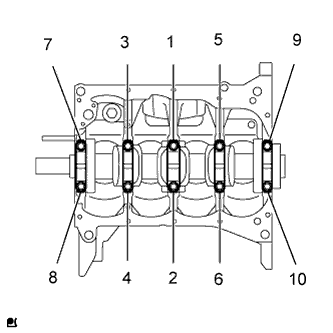
- Torque:
- 48 N*m{ 484 kgf*cm , 35 ft.*lbf }
Retighten the bolts, in several steps, in the sequence shown.
- Torque:
- 59 N*m{ 602 kgf*cm , 44 ft.*lbf }
Using several steps, loosen and remove the 10 crankshaft bearing cap set bolts uniformly in the sequence shown in the illustration.
Remove the crankshaft bearing caps.
Measure the plastigage at its widest point.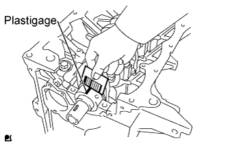
- Standard oil clearance:
- Standard bearing:
- 0.016 to 0.036 mm (0.00063 to 0.00142 in.)
- U/S (0.25) bearing:
- 0.015 to 0.055 mm (0.00059 to 0.00217 in.)
- Maximum oil clearance:
- 0.07 mm (0.0028 in.)
- NOTICE:
- Completely remove the plastigage after the measurement.
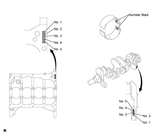
When replacing a standard bearing, replace it with one with the same number. If the number of the bearing cannot be found, select the correct bearing by adding together the numbers imprinted on the cylinder block and crankshaft, then select the bearing with the same number as the total. There are 4 sizes of standard bearings, marked 2, 3 ,4 and 5 accordingly.
- EXAMPLE:
- Cylinder Block Mark 1 + Crankshaft Mark 2 = Total 3 (Use Bearing Mark 3)
- Number mark:
Cylinder block
Crankshaft
Use bearing
1
1
2
1
2
3
2
1
3
2
2
4
3
1
4
3
2
5
Cylinder block main journal bore diameter: Mark 1
50.000 to 50.006 (1.96850 to 1.96874)
Mark 2
50.006 to 50.012 (1.96874 to 1.96898)
Mark 3
50.012 to 50.018 (1.96898 to 1.96921)
Crankshaft main journal diameter: Mark 1
45.994 to 46.000 (1.81079 to 1.81102)
Mark 2
45.988 to 45.994 (1.81055 to 1.81079)
Standard bearing center wall thickness: Mark 2
1.998 to 1.992 (0.07827 to 0.07843)
Mark 3
1.991 to 1.995 (0.07839 to 0.07854)
Mark 4
1.994 to 1.998 (0.07850 to 0.07866)
Mark 5
1.997 to 2.001 (0.07862 to 0.07878)
| 42. REMOVE CRANKSHAFT |
Remove the crankshaft.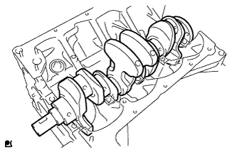
| 43. REMOVE CRANKSHAFT THRUST WASHER UPPER |
Remove the crankshaft thrust washer upper.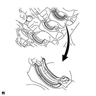
| 44. REMOVE CRANKSHAFT BEARING |
Remove the 5 crankshaft bearing lower.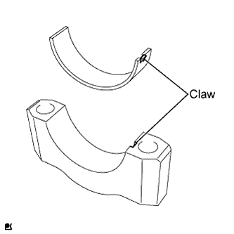
- HINT:
- Keep the crankshaft bearing cap and crankshaft bearing lower together.
- Keep the crankshaft bearing cap and crankshaft bearing lower in the correct order so that they can be returned to their original locations when reassembled.
- Keep the crankshaft bearing cap and crankshaft bearing lower together.
Remove the 5 crankshaft bearing uppers.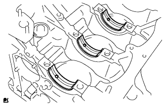
- HINT:
- Keep the crankshaft bearing upper, crankshaft bearing lower and crankshaft bearing cap together.
- Keep the crankshaft bearing upper, crankshaft bearing lower and crankshaft bearing cap in the correct order so that they can be returned to their original locations when reassembled.
- Keep the crankshaft bearing upper, crankshaft bearing lower and crankshaft bearing cap together.
| 45. REMOVE OIL REGULATOR ASSEMBLY |
Remove the oil regulator assembly.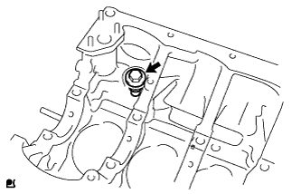
| 46. REMOVE CYLINDER BLOCK WATER DRAIN COCK PLUG |
Remove the cylinder block water drain cock plug.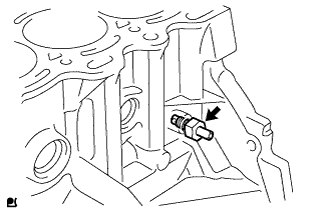
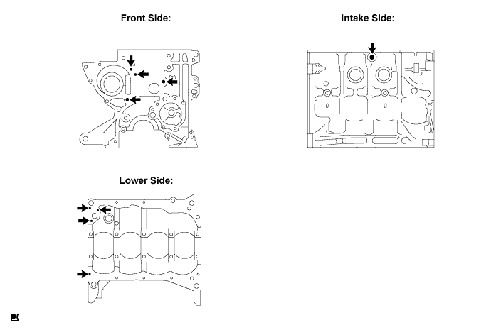
| 47. REMOVE STUD BOLT |
Remove the 9 stud bolts.
| 48. REMOVE RING PIN |
Remove the 2 ring pins.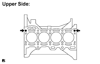
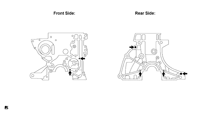
| 49. REMOVE STRAIGHT PIN |
Remove the 6 straight pins.
| 50. REMOVE PISTON RING SET |
- NOTICE:
- Keep the piston rings in the correct combination and correct order so that they can be returned to their original locations when re-assembling.
Using a piston ring expander, remove the 2 compression rings.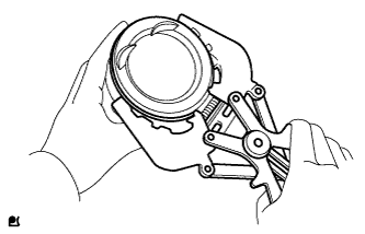
Remove the 2 side rails and the oil ring by hand.
| 51. REMOVE WITH PIN PISTON SUB-ASSEMBLY |
Using SST, press the piston pin out of the piston.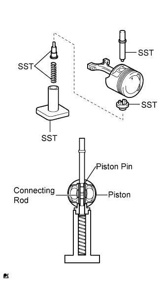
- SST
- 09221-25026
(09221-00021, 09221-00030, 09221-00130, 09221-00141, 09221-00150)
- NOTICE:
- Keep the piston, piston pin and connecting rod in the correct order so that they can be returned to their original locations when reassembled.