INSPECTION
Inspection · Vehicles built from Nov 2005
| INSPECT CAMSHAFT TIMING SPROCKET ASSEMBLY |

Check the lock of camshaft timing gear.
Clamp the camshaft in a vice, and check that the camshaft timing gear is locked.
- NOTICE:
- Do not damage the camshaft.
Release the lock pin.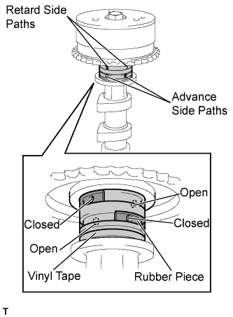

Cover the 4 oil paths of the cam journal with tape as shown in the illustration.
- HINT:
- One of the 2 grooves located on the cam journal is for retarding cam timing (upper) and the other is for advancing cam timing (lower). Each groove has 2 oil paths. Plug one of the oil paths for each groove with a piece of rubber before wrapping the cam journal with the tape.
Puncture the tape covering the advance oil path and the retard oil path on the opposite side from the advance oil path.
Apply air at about 100 kPa (1.0 kgf*cm2) pressure to the 2 broken paths (the advance side path and the retard side path).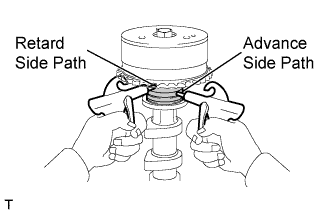
- NOTICE:
- Cover the paths with a shop rag or piece of cloth to prevent oil splashes.
Confirm that the camshaft timing gear assembly revolves in the timing advance direction when the air pressure on the timing retard path is reduced.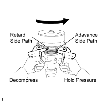
- HINT:
- The lock pin is released and the camshaft timing gear revolves in the advance direction.
When the camshaft timing gear reaches the most advanced position, release the air pressure on the timing retard side path, and then release the air pressure on the timing advance side path.
- NOTICE:
- Camshaft timing gear assembly occasionally shifts to the retard side abruptly if the air pressure on the advance side path is released first. This often results in breakage of the lock pin.
Check the revolution.
Rotate the valve timing assembly back and forth several times, except where the lock pin meets it at the most retarded angle. Check the movable range and that it rotates smoothly.
- Standard:
- Smooth movable range is about 30°.
- NOTICE:
- Perform this check by hand, instead of using air pressure.
Check the lock in the most retarded position.
Confirm that the camshaft timing gear assembly is locked in the most retarded position.
| INSPECT CHAIN SUB-ASSEMBLY |
Visually check the timing chain for wear and cracks. If the timing chain is not normal, replace the timing chain and check the sprocket.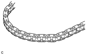
| INSPECT CHAIN TENSIONER PLUNGER |
Check that the plunger moves smoothly when the ratchet pawl is raised with your finger.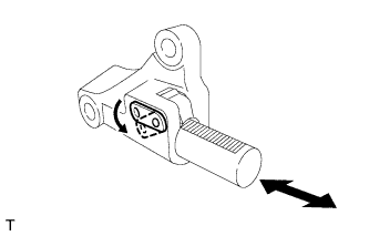
Release the ratchet pawl and check that the plunger is locked in place by the ratchet pawl and does not move when pushed with your finger.
| INSPECT CAMSHAFT TIMING SPROCKET ASSEMBLY |
Wrap the chain around the timing sprocket.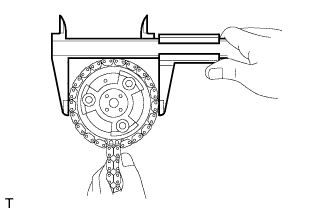
Using vernier calipers, measure the diameter of the timing gear with the chain.
- Minimum gear diameter (with chain):
- 90.2 mm (3.551 in.)
- NOTICE:
- Make sure that the vernier calipers are in contact with the chain link when measuring.
| INSPECT CAMSHAFT TIMING GEAR OR SPROCKET |
Wrap the chain around the timing sprocket.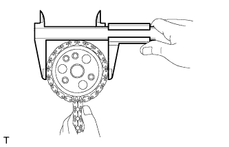
Using vernier calipers, measure the diameter of the timing gear with the chain.
- Minimum gear diameter (with chain):
- 90.2 mm (3.551 in.)
- NOTICE:
- Make sure that the vernier calipers are in contact with the chain link when measuring.
| INSPECT OIL PUMP ASSEMBLY |
Wrap the chain around the oil pump sprocket.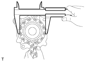
Using vernier calipers, measure the diameter of the timing gear with the chain.
- Minimum gear diameter (with chain):
- 55.8 mm (2.197 in.)
- NOTICE:
- Make sure that the vernier calipers are in contact with the chain link when measuring.
| INSPECT CRANKSHAFT TIMING GEAR OR SPROCKET |
Wrap the chain around the timing sprocket.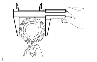
Using vernier calipers, measure the diameter of the timing gear with the chain.
- Minimum gear diameter (with chain):
- 47.7 mm (1.878 in.)
- NOTICE:
- Make sure that the vernier calipers are in contact with the chain link when measuring.
| INSPECT TIMING CHAIN TENSION ARM |
Check the chain tension arm.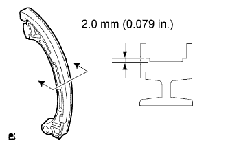
- Minimum thickness:
- 2.0 mm (0.079 in.)
| INSPECT TIMING CHAIN GUIDE |
Check the vibration damper.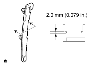
- Minimum thickness:
- 2.0 mm (0.079 in.)
| INSPECT CYLINDER BLOCK FOR WARPAGE |
Using a precision straight edge and feeler gauge, measure the warpage of the surface which is in contact with the cylinder head gasket.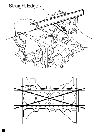
- Maximum warpage:
- 0.05 mm (0.0020 in.)
| INSPECT CYLINDER BORE |
Using a cylinder gauge, measure the cylinder bore diameter at positions A and B in the thrust and axial directions.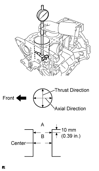
- Standard inside diameter:
- 72.000 to 72.013 mm (2.83465 to 2.83516 in.)
- Maximum inside diameter:
- 72.200 mm ( 2.84252 in.)
| INSPECT PISTON OIL CLEARANCE |
Using a micrometer, measure the piston diameter at a right angle to the piston pin center line, and at the position 10.0 mm (0.394 in.) from the piston skirt.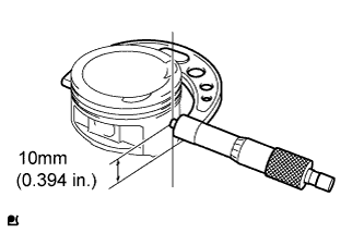
- Piston diameter:
- 71.946 to 71.960 mm (2.83252 to 2.83307 in.)
Subtract the piston diameter measurement from the cylinder bore diameter measurement to calculate the oil clearance.
- Standard oil clearance:
- 0.040 to 0.067 mm (0.00157 to 0.00264 in.)
- Maximum oil clearance:
- 0.10 mm (0.0039 in.)
| INSPECT PISTON PIN OIL CLEARANCE |
Using a caliper gauge, measure the piston pin hole diameter.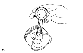
- Piston pin hole diameter:
- 18.006 to 18.010 mm (0.70890 to 0.70906 in.) at 20°C (68°F)
Using a micrometer, measure the piston pin diameter.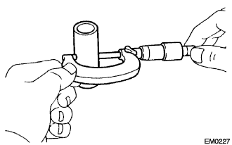
- Piston pin diameter:
- 17.997 to 18.000 mm (0.70854 to 0.70866 in.)
Subtract the piston pin diameter measurement from the piston pin hole diameter measurement to calculate the oil clearance.
- Standard oil clearance:
- 0.006 to 0.013 mm (0.00024 to 0.00051 in.)
- Maximum oil clearance:
- 0.050 mm (0.0020 in.)
| INSPECT RING GROOVE CLEARANCE |
Using a feeler gauge, measure the clearance between a new piston ring and the wall of the ring groove.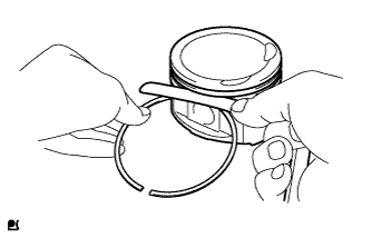
- Ring groove clearance:
- No. 1:
- 0.030 to 0.070 mm (0.00118 to 0.00276 in.)
- No. 2:
- 0.020 to 0.060 mm (0.00079 to 0.00236 in.)
- Oil:
- 0.070 to 0.150 mm (0.00276 to 0.00591 in.)
| INSPECT PISTON RING END GAP |
Using a piston, push the piston ring, a little beyond the bottom of the ring travel, 110 mm (4.33 in.) from the top of the cylinder block.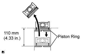
Using a feeler gauge, measure the end gap.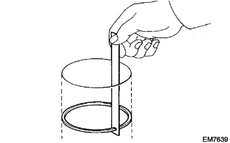
- Standard end gap:
- No. 1:
- 0.20 to 0.30 mm (0.0079 to 0.0118 in.)
- No. 2:
- 0.40 to 0.55 mm (0.0157 to 0.0217 in.)
- Oil (Side Rail):
- 0.10 to 0.35 mm (0.0039 to 0.0138 in.)
- Maximum end gap:
- No. 1:
- 0.79 mm (0.0311 in.)
- No. 2:
- 0.80 mm (0.0315 in.)
- Oil (Side Rail):
- 0.59 mm (0.0232 in.)
| INSPECT CONNECTING ROD SUB-ASSEMBLY |
Using a rod aligner and feeler gauge, check the connecting rod alignment.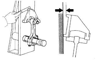
Check for misalignment.
- Maximum misalignment:
- 0.05 mm (0.0020 in.) per 100 mm (3.94 in.)
Check for twist.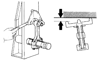
- Maximum twist:
- 0.05 mm (0.0020 in.) per 100 mm (3.94 in.)
| INSPECT CONNECTING ROD BOLT |
Using vernier calipers, measure the minimum diameter of the elongated thread at measuring position A.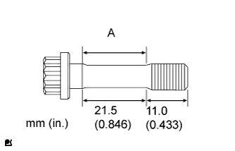
- Minimum outside diameter:
- 6.4 mm (0.252 in.)
- HINT:
- If the outside diameter is less than minimum, replace the connecting rod bolt.
| INSPECT CRANKSHAFT |
Using a dial indicator and V-blocks, measure the circle runout as shown in the illustration.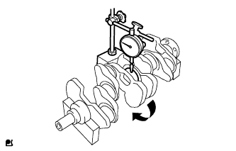
- Maximum circle runout:
- 0.03 mm (0.0012 in.)
Using a micrometer, measure the diameter of each main journal.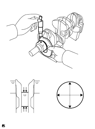
- Outside Diameter:
- 45.988 to 46.000 mm (1.81055 to 1.81102 in.)
Check each main journal for taper and out-of-roundness as shown.
- Maximum taper and out-of-roundness:
- 0.02 mm (0.0008 in.)
Using a micrometer, measure the diameter of each crank pin.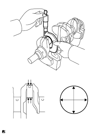
- Outside Diameter:
- 39.992 to 40.000 mm (1.57449 to 1.57480 in.)
Check each crank pin for taper and out-of-roundness as shown.
- Maximum taper and out-of-roundness:
- 0.02 mm (0.0008 in.)