REASSEMBLY
Removal / installation · Vehicles built from Nov 2005
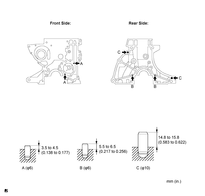
| 1. INSTALL STRAIGHT PIN |

Using a plastic-faced hammer, tap in a new straight pin.
- Standard protrusion:
- Pin A:
- 3.5 to 4.5 mm (0.138 to 0.177 in.)
- Pin B:
- 5.5 to 6.5 mm (0.217 to 0.256 in.)
- Pin C:
- 14.8 to 15.8 mm (0.583 to 0.622 in.)

| 2. INSTALL RING PIN |
Using a plastic-faced hammer, tap in a new ring pin.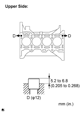
- Standard protrusion:
- 5.2 to 6.8 mm (0.205 to 0.268 in.)
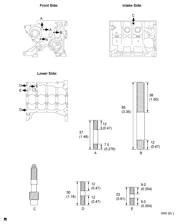
| 3. INSTALL STUD BOLT |
Install the 9 stud bolts.
- Torque:
- Bolt A, D, E:
- 4.0 N*m{ 41 kgf*cm , 35 in.*lbf }
- Bolt B:
- 6.0 N*m{ 61 kgf*cm , 53 in.*lbf }
- Bolt C:
- 11 N*m{ 112 kgf*cm , 8 ft.*lbf }
- NOTICE:
- The lower threads of the bolt are installed into the cylinder block.
| 4. INSTALL CYLINDER BLOCK WATER DRAIN COCK PLUG |
Install the cylinder block water drain cock plug.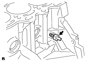
- Torque:
- 30 N*m{ 306 kgf*cm , 22 ft.*lbf }
| 5. INSTALL OIL REGULATOR ASSEMBLY |
Install the oil regulator assembly.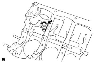
- Torque:
- 40 N*m{ 408 kgf*cm , 30 ft.*lbf }
| 6. INSTALL CRANKSHAFT BEARING |
Align the bearing claws with the claw grooves of the cylinder block, and push in the 5 crankshaft bearing uppers.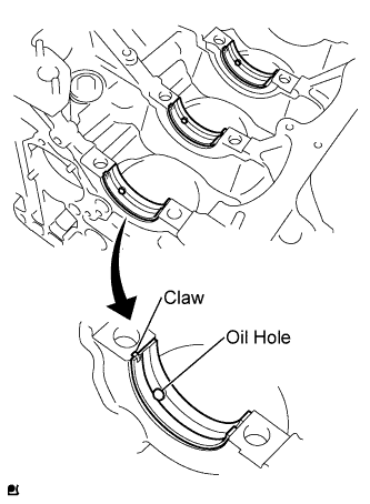
- NOTICE:
- Install the bearing while aligning with the oil hole in the cylinder block.
- Do not apply engine oil to the installation face.
- Install the bearing while aligning with the oil hole in the cylinder block.
Align the bearing claws with the claw grooves of the crankshaft bearing cap, and push in the 5 crankshaft bearing lowers.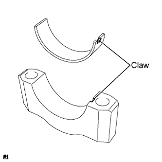
- NOTICE:
- Do not apply engine oil to the installation face.
| 7. INSTALL CRANKSHAFT |
Apply a light coat of engine oil to the crankshaft bearing upper and install the crankshaft onto the cylinder block.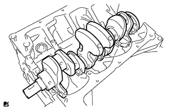
Install the 2 thrust washers onto the No. 3 journal position of the cylinder block with the oil grooves facing outward.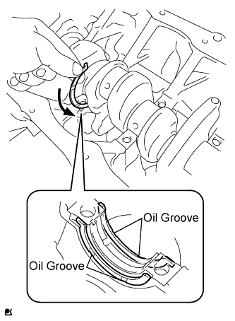
- HINT:
- Slide the thrust washer into the gap between the cylinder block and the crankshaft, starting with the end without the claw, to install it.
Apply light coat of engine oil to the crankshaft bearing lower.
Examine the front marks and numbers and install the bearing cap onto the cylinder block.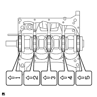
Apply a light coat of engine oil to the threads of the bearing cap bolts.
Install and uniformly tighten the bolts, in several steps, in the sequence shown.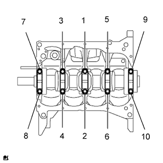
- Torque:
- 48 N*m{ 484 kgf*cm , 35 ft.*lbf }
Retighten the bolts, in several steps, in the sequence shown.
- Torque:
- 59 N*m{ 602 kgf*cm , 44 ft.*lbf }
Check that the crankshaft turns smoothly.
| 8. INSPECT CRANKSHAFT THRUST CLEARANCE |
Using a dial indicator, measure the thrust clearance while moving the crankshaft back and forth with a screwdriver.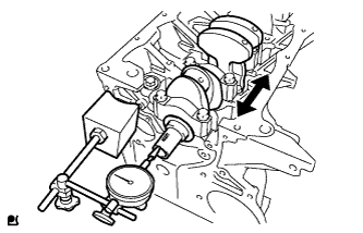
- Standard thrust clearance:
- 0.020 to 0.220 mm (0.00079 to 0.00866 in.)
- Maximum thrust clearance:
- 0.30 mm (0.0118 in.)
- Thrust washer thickness:
Type
mm (in.)
STD
1.940 to 1.990 (0.07638 to 0.07825)
O/S (0.125)
2.062 to 2.115 (0.08130 to 0.08327)
O/S (0.250)
2.190 to 2.240 (0.08622 to 0.08819)
| 9. INSPECT CRANKSHAFT OIL CLEARANCE |
Using several steps, loosen and remove the 10 crankshaft bearing cap set bolts uniformly in the sequence shown in the illustration.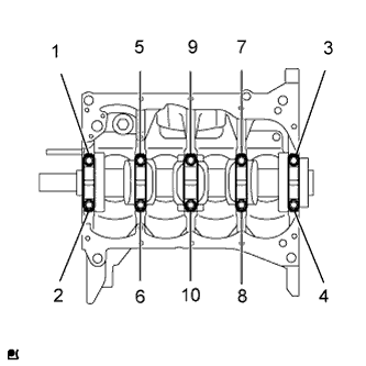
Remove the crankshaft bearing cap.
Clean each main journal and bearing.
Lay a strip of Plastigage across each journal.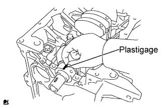
- NOTICE:
- Do not turn the crankshaft.
Examine the front marks and numbers and install the bearing cap onto the cylinder block.
Apply a light coat of engine oil to the threads of the bearing cap bolts.
Install and uniformly tighten the bolts, in several steps, in the sequence shown.
- Torque:
- 48 N*m{ 484 kgf*cm , 35 ft.*lbf }
Retighten the bolts, in several steps, in the sequence shown.
- Torque:
- 59 N*m{ 602 kgf*cm , 44 ft.*lbf }
Using several steps, loosen and remove the 10 crankshaft bearing cap set bolts uniformly in the sequence shown in the illustration.
Remove the crankshaft bearing caps.
Measure the plastigage at its widest point.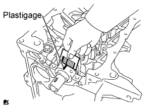
- Standard oil clearance:
- Standard bearing:
- 0.016 to 0.036 mm (0.00063 to 0.00142 in.)
- U/S (0.25) bearing:
- 0.015 to 0.055 mm (0.00059 to 0.00217 in.)
- Maximum oil clearance:
- 0.07 mm (0.0028 in.)
- NOTICE:
- Completely remove the plastigage after the measurement.
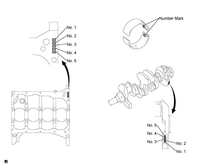
When replacing a standard bearing, replace it with one with the same number. If the number of the bearing cannot be found, select the correct bearing by adding together the numbers imprinted on the cylinder block and crankshaft, then select the bearing with the same number as the total. There are 4 sizes of standard bearings, marked 2, 3 ,4 and 5 accordingly.
- EXAMPLE:
- Cylinder Block Mark 1 + Crankshaft Mark 2 = Total 3 (Use Bearing Mark 3)
- Number mark:
Cylinder block
Crankshaft
Use bearing
1
1
2
1
2
3
2
1
3
2
2
4
3
1
4
3
2
5
Cylinder block main journal bore diameter: Mark 1
50.000 to 50.006 (1.96850 to 1.96874)
Mark 2
50.006 to 50.012 (1.96874 to 1.96898)
Mark 3
50.012 to 50.018 (1.96898 to 1.96921)
Crankshaft main journal diameter: Mark 1
45.994 to 46.000 (1.81079 to 1.81102)
Mark 2
45.988 to 45.994 (1.81055 to 1.81079)
Standard bearing center wall thickness: Mark 2
1.998 to 1.992 (0.07827 to 0.07843)
Mark 3
1.991 to 1.995 (0.07839 to 0.07854)
Mark 4
1.994 to 1.998 (0.07850 to 0.07866)
Mark 5
1.997 to 2.001 (0.07862 to 0.07878)
| 10. INSTALL WITH PIN PISTON SUB-ASSEMBLY |
Coat the piston pin and pin holes in the piston with engine oil.
Align the cavity of the piston with the protruded portion on the connecting rod.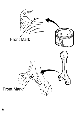
Using SST, press in the piston pin.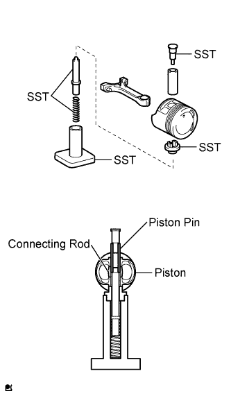
- SST
- 09221-25026
(09221-00021, 09221-00030, 09221-00130, 09221-00141, 09221-00150)
Check that the piston pin is pressed in to the position shown in the illustration.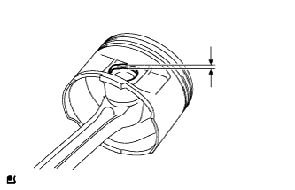
- Standard clearance:
- 2.8 to 4.0 mm (0.110 to 0.157 in.)
| 11. INSTALL CONNECTING ROD BEARING SET |
Align the bearing claw with the groove of the connecting rod.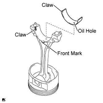
- NOTICE:
- Clean the back side of the bearing and the bearing surface of the connecting rod and keep them free of oil.
Align the bearing claw with the groove of the connecting rod cap.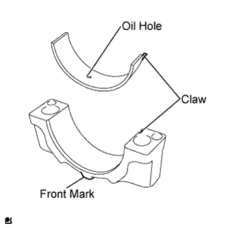
- NOTICE:
- Clean the back side of the bearing and the bearing surface of the connecting rod cap and keep them free of oil.
| 12. INSTALL PISTON RING SET |
Install the oil ring expander and 2 side rails by hand.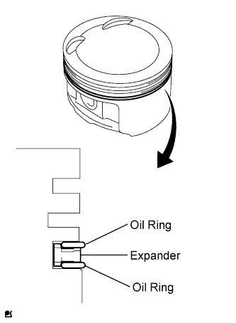
Using a piston ring expander, install the compression No. 2 ring with its code mark T facing upward.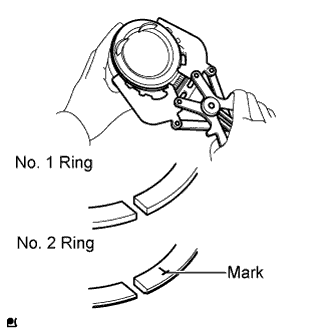
Using a piston ring expander, install the compression ring.
Position the piston rings so that the ring ends are as shown.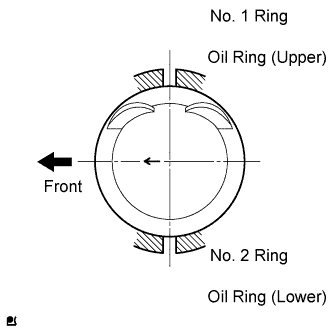
| 13. INSTALL WITH PIN PISTON SUB-ASSEMBLY |
Apply engine oil to the cylinder walls, the pistons, and the surfaces of connecting rod bearings.
Check the position of the piston ring ends.
Using a piston ring compressor, push the correctly numbered piston and connecting rod assemblies into each cylinder with the front mark on the piston facing forward.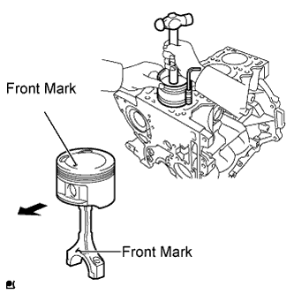
- NOTICE:
- Do not damage the cylinder block and crankshaft when installing the piston sub-assembly.
Make sure that the connecting rod and its connecting rod cap are in the correct combination and that the front mark of the cap is facing in the correct mounting orientation, then install the cap onto the connecting rod.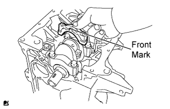
Apply a light coat of engine oil to the threads of the connecting rod cap bolts.
Using SST, tighten the bolts in several steps to the specified torque.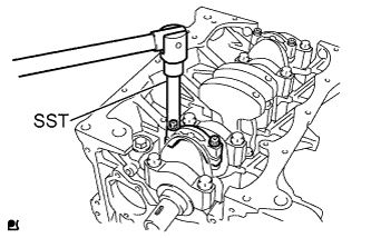
- SST
- 09205-16010
- Torque:
- 22 N*m{ 224 kgf*cm , 16 ft.*lbf }
Mark the front of the connecting cap bolts with paint.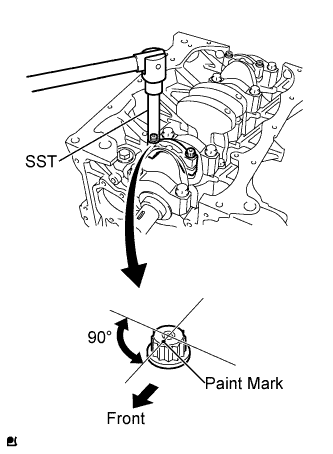
Retighten the connecting rod cap bolts by 90° as shown in the illustration.
Check that the crankshaft turns smoothly.
| 14. INSPECT CONNECTING ROD THRUST CLEARANCE |
| 15. INSPECT CONNECTING ROD OIL CLEARANCE |
| 16. INSTALL ENGINE REAR OIL SEAL |
Apply MP grease to a new oil seal lip.
- NOTICE:
- Keep the lip free of foreign matter.
Using SST, tap in the new oil seal.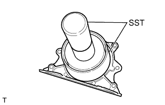
- SST
- 09223-15020
(09951-07100)
- NOTICE:
- Do not tap the oil seal at an angle.
- Wipe any extra grease off the crankshaft.
- Do not tap the oil seal at an angle.
| 17. INSTALL ENGINE REAR OIL SEAL RETAINER |
Apply a continuous bead of seal packing (Diameter 3 to 4 mm (0.12 to 0.16 in.)) as shown in the illustration.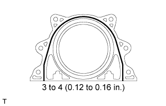
- Seal packing:
- 08826-00080 or the equivalent
Install the oil seal retainer with the 4 bolts.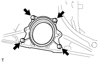
- Torque:
- 8.5 N*m{ 87 kgf*cm , 75 in.*lbf }
| 18. INSTALL OIL PIPE ASSEMBLY |
Install a new O-ring.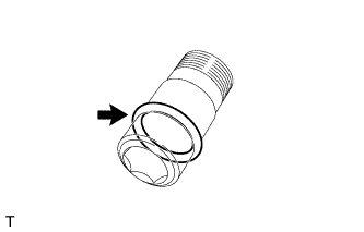
Using a 12 mm hexagon wrench, install the oil pipe assembly.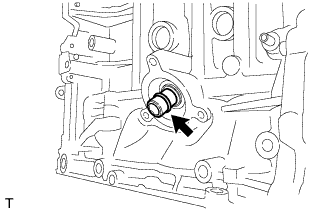
- Torque:
- 44 N*m{ 449 kgf*cm , 33 ft.*lbf }
- NOTICE:
- Do not damage the O-ring of the oil pipe assembly.
| 19. INSTALL OIL FILTER BRACKET SUB-ASSEMBLY |
Install a new O-ring.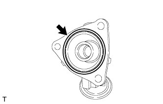
Install the oil filter bracket sub-assembly with the 3 bolts.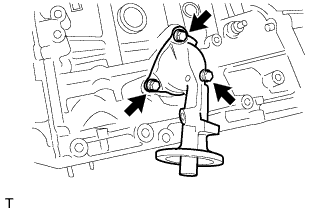
- Torque:
- 18 N*m{ 184 kgf*cm , 13 ft.*lbf }
| 20. INSTALL OIL FILTER BRACKET |
Install the oil filter bracket with the 2 bolts.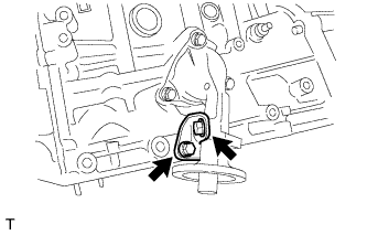
- Torque:
- 18 N*m{ 184 kgf*cm , 13 ft.*lbf }
| 21. INSTALL OIL FILTER SUB-ASSEMBLY |
Check and clean the oil filter installation surface.
Apply clean engine oil to the O-ring of a new oil filter.
Gently screw the oil filter into place, then tighten it until the gasket comes into contact with the seat.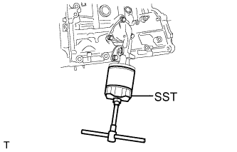
Using SST, tighten the oil filter.
- SST
- 09228-06501
Depending on the work space available, choose from the following.
If enough space is available, use a torque wrench to tighten the oil filter.- Torque:
- 13 N*m{ 133 kgf*cm , 10 ft.*lbf }
| 22. INSTALL CYLINDER HEAD GASKET |
Place a new cylinder head gasket on the cylinder block with the Lot No. stamp facing upward.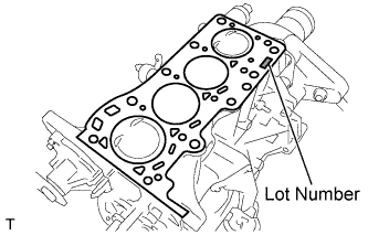
- NOTICE:
- Remove any oil from the contact surfaces.
- Check the mounting orientation of the cylinder head gasket.
- Do not damage the cylinder gasket when installing the cylinder head onto the cylinder block.
- Remove any oil from the contact surfaces.
| 23. INSTALL CYLINDER HEAD SUB-ASSEMBLY |
- HINT:
- The cylinder head bolts are tightened in 2 successive steps.
Apply a light coat of engine oil to the threads of the cylinder head bolts.
Using several steps, install and tighten the 10 cylinder head bolts and plate washers uniformly with an 8 mm bi-hexagon wrench, in the sequence shown in the illustration.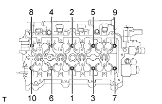
- Torque:
- 34 N*m{ 347 kgf*cm , 25 ft.*lbf }
Mark the front of the cylinder head bolt with paint.
Tighten the cylinder head bolts 90° and then an additional 90° as shown in the illustration.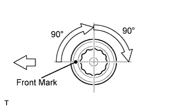
Check that the paint mark is now at a 180° angle from the front.
Apply a continuous bead of seal packing (Diameter 2.3 mm 0.091 in.)) as shown in the illustration.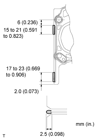
- Seal Packing:
- Toyota genuine seal packing black, Three bond 12078B or Equivalent.
- NOTICE:
- Remove any oil from the contact surfaces.
- Install the oil pump assembly within 3 minutes and tighten the bolts within 15 minutes of applying the seal packing.
- Remove any oil from the contact surfaces.
| 24. INSTALL CAMSHAFT TIMING GEAR OR SPROCKET |
Install the camshaft timing gear or sprocket with the 3 bolts.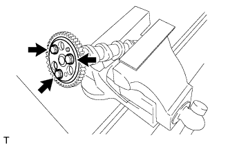
- Torque:
- 8.0 N*m{ 82 kgf*cm , 71 in.*lbf }
| 25. INSTALL CAMSHAFT |
Apply new engine oil to the valve lifter and the journal of the cylinder head.
Place the intake camshaft on the cylinder head so that the cam noses of cylinders No. 3 and No. 4 face as shown in the illustration.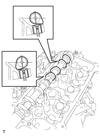
Apply new engine oil to the lifter and journal of the cylinder head.
Place the exhaust camshaft on the cylinder head so that the cam noses of cylinders No. 2 and No. 4 face as shown in the illustration.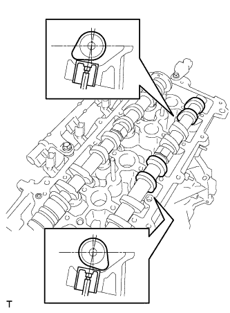
Make sure that the bearing caps are in the sequence shown in the illustration and install the bearing caps with the 8 bolts.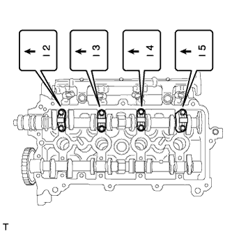
Make sure that the bearing caps are in the sequence shown in the illustration and install the bearing caps with the 8 bolts.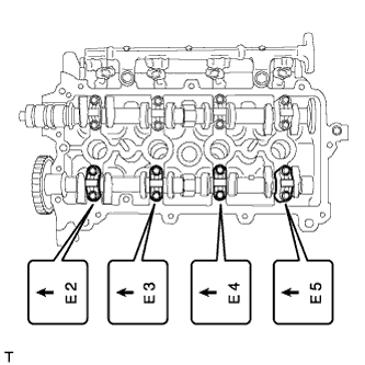
Provisionally install the camshaft bearing cap with the 4 bolts, as shown the illustration.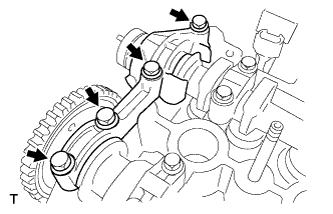
Uniformly tighten the 20 bolts in several steps in the sequence shown in the illustration.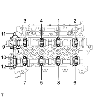
- Torque:
- 13 N*m{ 127 kgf*cm , 9 ft.*lbf }
| 26. INSTALL CAMSHAFT TIMING SPROCKET ASSEMBLY |
Using the hexagonal portion of the camshaft, hold the camshaft and install the camshaft timing sprocket with the bolt.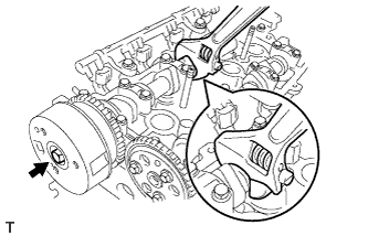
- Torque:
- 47 N*m{ 479 kgf*cm , 35 ft.*lbf }
| 27. INSTALL OIL PUMP ASSEMBLY |
Apply sufficient engine oil to the locations shown in the illustration.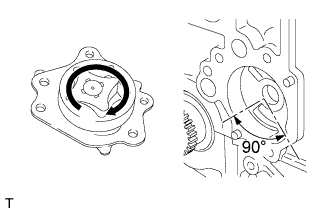
- HINT:
- Apply engine oil between the teeth of the inner and outer rotors.
- Apply engine oil to the lower side of the rotor hole of the cylinder block (application range of 90° or more).
- Apply engine oil between the teeth of the inner and outer rotors.
Make sure that the oil pump is free of foreign matter and install the oil pump with the 3 bolts.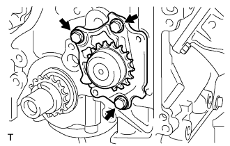
- Torque:
- 9.0 N*m{ 92 kgf*cm , 80 in.*lbf }
After installing the oil pump, turn the sprocket 360 degrees or more to apply oil to the entire rotor and make sure that the rotor turns smoothly.
| 28. INSTALL NO. 1 OIL NOZZLE SUB-ASSEMBLY |
Install the oil nozzle with the bolt.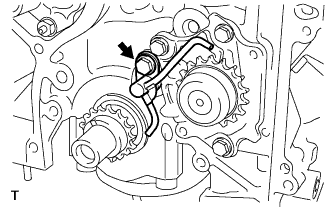
- Torque:
- 7.5 N*m{ 76 kgf*cm , 66 in.*lbf }
| 29. INSTALL CRANKSHAFT TIMING GEAR OR SPROCKET |
Install the woodruff key and the crankshaft timing gear or sprocket.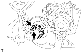
| 30. INSTALL CHAIN SUB-ASSEMBLY |
Align the mark plates of the chain with the matchmarks of the crankshaft sprocket and install the timing chain.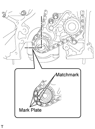
Align the mark plates of the chain with the matchmarks of the camshaft timing sprocket and camshaft timing gear and install the timing chain.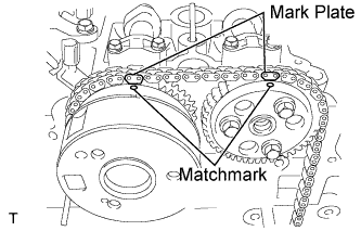
| 31. INSTALL NO. 2 TIMING CHAIN GUIDE |
Install the No. 2 timing chain guide with the 2 bolts.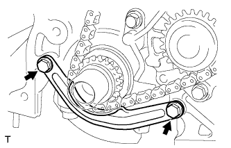
- Torque:
- 12 N*m{ 122 kgf*cm , 9 ft.*lbf }
| 32. INSTALL TIMING CHAIN GUIDE |
Install the timing chain guide with the 2 bolts.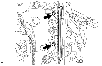
- Torque:
- 7.5 N*m{ 76 kgf*cm , 66 in.*lbf }
| 33. INSTALL TIMING CHAIN TENSION ARM |
Install the timing chain tension arm with the bolt.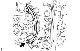
- Torque:
- 19 N*m{ 194 kgf*cm , 14 ft.*lbf }
| 34. INSTALL CHAIN TENSIONER PLUNGER |
Install the chain tensioner plunger with the bolt and the nut.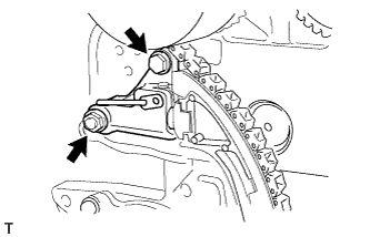
- Torque:
- 9.0 N*m{ 92 kgf*cm , 80 in.*lbf }
- NOTICE:
- Using the hexagonal portion of the camshaft, slightly turn the camshaft counterclockwise and install the tensioner plunger with the chain on the tensioner loose.
Remove the 3 mm diameter bar from the chain tensioner plunger.
| 35. INSTALL NO. 1 CRANKSHAFT POSITION SENSOR PLATE |
Install the No. 1 crankshaft position sensor plate so that mark F can be seen.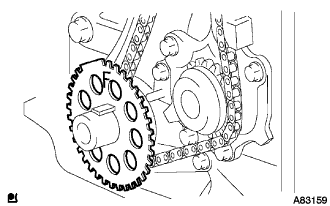
| 36. INSTALL TIMING CHAIN OR BELT COVER OIL SEAL |
Using SST, tap in a new oil seal to the specified depth.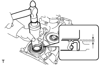
- SST
- 09636-20010
- NOTICE:
- Do not tap in the oil seal in at an angle.
Apply a small amount of MP grease to the lip of the new oil seal.
- NOTICE:
- Keep the lip free of foreign matter.
| 37. INSTALL TIMING CHAIN OR BELT COVER SUB-ASSEMBLY |
Install a new gasket onto the timing chain cover.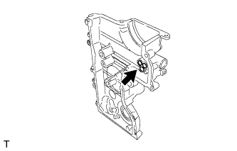
Apply seal packing black as shown in the illustration.
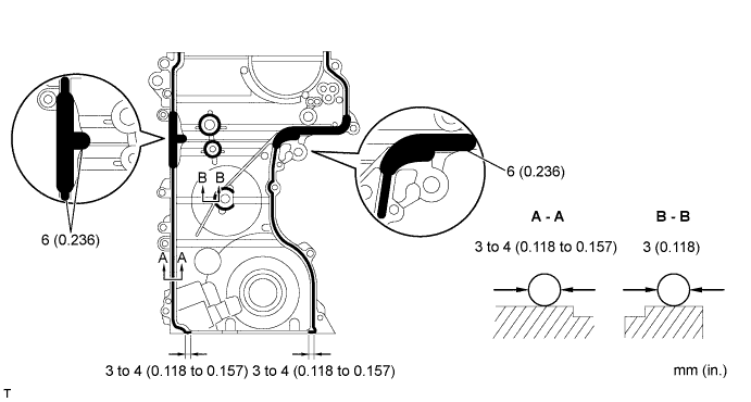
- Seal packing:
- Toyota genuine seal packing black, Three bond 12078B or Equivalent.
- NOTICE:
- Remove any oil from the contact surfaces.
- Install the oil pump assembly within 3 minutes and tighten the bolts and nut within 15 minutes of applying seal packing.
- Do not expose the seal to engine oil for at least 2 hours after the installation.
- Remove any oil from the contact surfaces.
Install the 10 bolts and nut.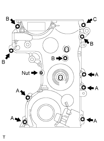
- Torque:
- 12 N*m{ 122 kgf*cm , 9 ft.*lbf } bolt A or B
- 23 N*m{ 238 kgf*cm , 17 ft.*lbf } bolt C
- 12 N*m{ 122 kgf*cm , 9 ft.*lbf } nut
- HINT:
- Each bolt length is as follows.
- A: 10 mm (0.394 in.)
- B: 30 mm (1.181 in.)
- C: 35 mm (1.378 in.)
- A: 10 mm (0.394 in.)
| 38. INSTALL OIL STRAINER SUB-ASSEMBLY |
Install a new gasket.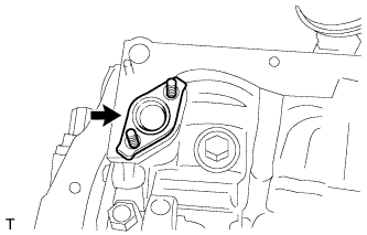
Install the oil strainer with the 2 nuts and bolt.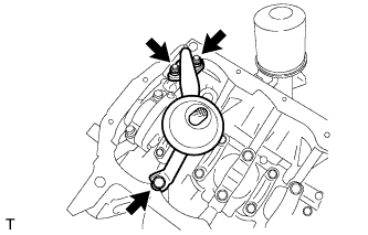
- Torque:
- 8.5 N*m{ 87 kgf*cm , 75 in.*lbf }
| 39. INSTALL OIL PAN SUB-ASSEMBLY |
Apply seal packing black (Diameter 4.0 mm 0.157 in.) to the area shown in the illustration.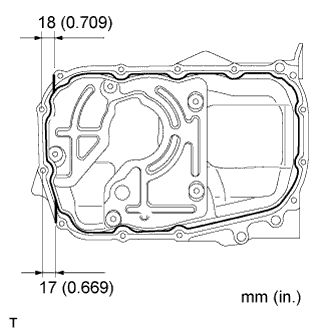
- Seal packing:
- Toyota genuine seal packing black, Three bond 12078B or Equivalent.
- NOTICE:
- Keep the installation surfaces free of oil.
- Install the oil pan within 3 minutes of applying seal packing black.
- Install the oil pan to the specified torque within 15 minutes of applying seal packing black.
- Do not start the engine within 2 hours of installation.
- Keep the installation surfaces free of oil.
Install the oil pan with the 12 bolts and 2 nuts.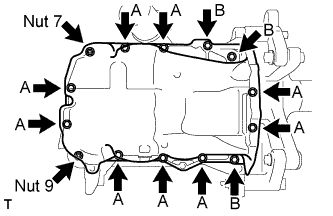
- Torque:
- 9.0 N*m{ 92 kgf*cm , 80 ft.*lbf } bolt A
- 41 N*m{ 413 kgf*cm , 30 ft.*lbf } bolt B
- 13 N*m{ 133 kgf*cm , 10 ft.*lbf } nut
| 40. INSTALL TRANSVERSE ENGINE ENGINE MOUNTING BRACKET |
Install the engine mounting bracket with the 2 bolts and nut.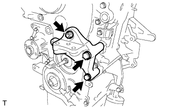
- Torque:
- 42 N*m{ 428 kgf*cm , 31 ft.*lbf }
| 41. INSTALL ENGINE MOUNTING STAY RH |
Install the engine mounting stay with the 2 bolts.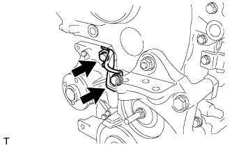
- Torque:
- 18 N*m{ 184 kgf*cm , 13 ft.*lbf }
| 42. INSTALL CRANKSHAFT PULLEY |
w/o service hole: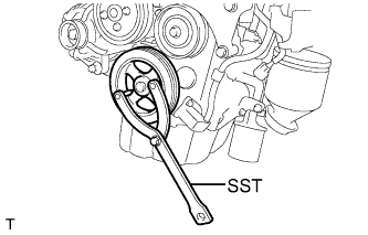
Hold the crankshaft pulley with SST and tighten the bolt.
- Torque:
- 150 N*m{ 1,530 kgf*cm , 111 ft.*lbf }
- SST
- 09960-10010
(09963-00500)
w/ service hole: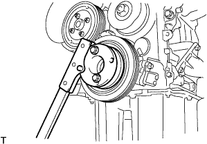
Hold the crankshaft pulley with SST and tighten the bolt.
- Torque:
- 150 N*m{ 1,530 kgf*cm , 111 ft.*lbf }
- SST
- 09330-00021
09213-54015 (91651-60855)
| 43. INSPECT VALVE CLEARANCE |
Turn the crankshaft pulley clockwise and position the timing mark (cutout) as shown in the illustration.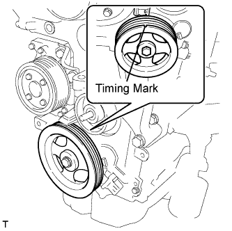
Make sure that the timing marks of the camshaft timing sprocket and the camshaft timing gear are in the positions shown in the illustration.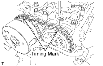
- HINT:
- If the timing marks are not aligned, turn the crankshaft 1 complete revolution and align the marks as above.
Check the valves indicated in the illustration.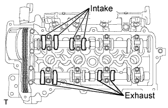
Using a feeler gauge, measure the clearance between the valve lifter and camshaft.
- Valve clearance (cold):
- for intake:
- 0.15 to 0.24 mm (0.006 to 0.009 in.)
- for exhaust:
- 0.22 to 0.31 mm (0.009 to 0.012 in.)
Record any out-of-specification valve clearance measurements. They will be used later to determine the required replacement adjusting shim.
Turn the crankshaft 1 complete revolution (360°) and align its timing notch with the timing mark "0" of the oil pump.
Check the valves indicated in the illustration.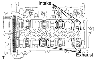
Using a feeler gauge, measure the clearance between the valve lifter and camshaft.
- Valve clearance (cold):
- for intake:
- 0.15 to 0.24 mm (0.006 to 0.009 in.)
- for exhaust:
- 0.22 to 0.31 mm (0.009 to 0.012 in.)
Record any out-of-specification valve clearance measurements. They will be used later to determine the required replacement adjusting shim.
| 44. ADJUST VALVE CLEARANCE |
Remove the 2 bolts and remove the No. 2 timing chain or belt cover.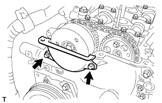
Turn the crankshaft pulley clockwise and remove the 2 bolts.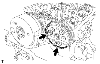
Turn the crankshaft pulley clockwise and position the timing mark (cutout) as shown in the illustration.
Make sure that the timing marks of the camshaft timing sprocket and the camshaft timing gear are in the positions shown in the illustration.
- HINT:
- If the timing marks are not aligned, turn the crankshaft 1 complete revolution and align the marks as above.
Place paint marks on the chain plate corresponding to the timing marks of the camshaft timing gear and the camshaft timing sprocket.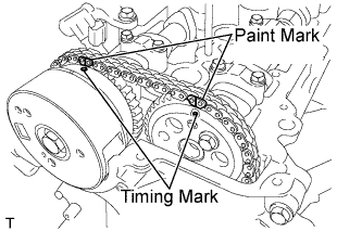
Using the hexagonal portion of the camshaft, loosen the camshaft timing sprocket fixing bolt.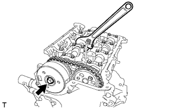
Using a socket hexagonal wrench 10, remove the chain cover service hole screw plug.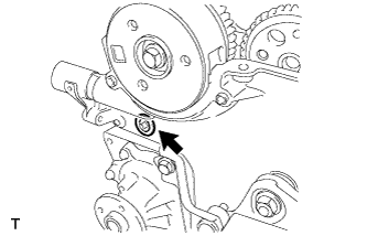
Using a screwdriver, pull down the stopper plate of the tensioner from the chain tensioner service hole and hold it.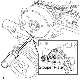
- HINT:
- If the lock of the stopper plate is hard to release, using the hexagonal portion of the camshaft, turn the camshaft slightly both ways.
Using the hexagonal portion of the camshaft, turn the camshaft slightly clockwise and hold it.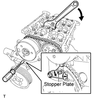
- HINT:
- The plunger of the tensioner is pushed by turning the camshaft clockwise.
Remove the screwdriver from the chain tensioner service hole, then align the holes in the stopper plate and the tensioner and insert a 3 mm diameter bar into the holes to hold the stopper plate.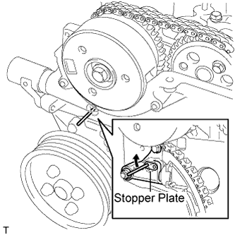
- NOTICE:
- If the 3 mm diameter bar is hard to insert into the holes, turn the camshaft slightly counterclockwise and clockwise.
- Using the hexagonal portion of the camshaft, hold the camshaft.
- Securely hold the bar with tape so that the bar does not come off.
- If the 3 mm diameter bar is hard to insert into the holes, turn the camshaft slightly counterclockwise and clockwise.
Remove the installation bolt from the camshaft timing gear or sprocket and remove the sprocket from the exhaust camshaft.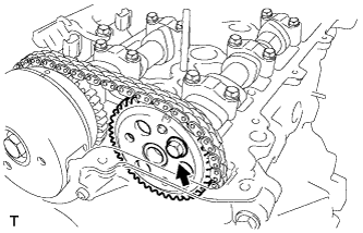
Remove the bolt and remove the camshaft timing sprocket assembly.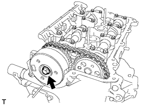
Turn the crankshaft pulley 90 degrees.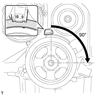
- NOTICE:
- When turning the camshaft with the chain removed, turn the crankshaft 90 degrees clockwise to avoid it interfering with the piston when the valve is fully open. Make sure that the cutout of the crankshaft pulley is in the position shown in the illustration.
Remove the 4 bolts and the camshaft bearing cap.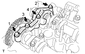
Using the hexagonal head portion of the camshaft, revolve the camshaft so that the cam noses of cylinders No. 2 and No. 4 face as shown in the illustration.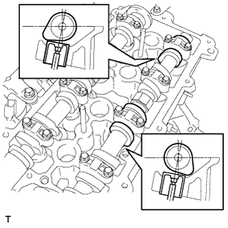
Remove the camshaft bearing caps and bolts in the sequence shown in the illustration.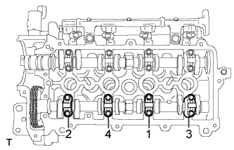
Remove the exhaust camshaft assembly.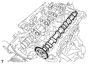
Using the hexagonal head portion of the camshaft, revolve the camshaft so that the cam noses of cylinders No. 3 and No. 4 face as shown in the illustration.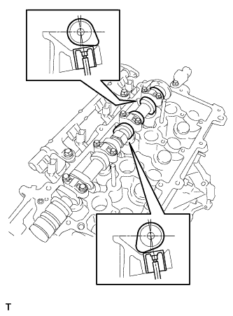
Remove the camshaft bearing caps in the sequence shown in the illustration.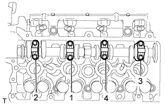
Remove the camshaft.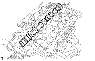
Fix the chain with a piece of rope or wire.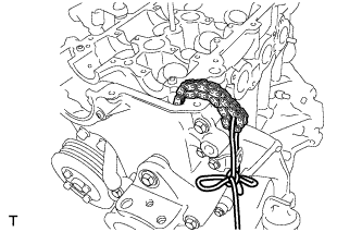
Remove the valve lifters.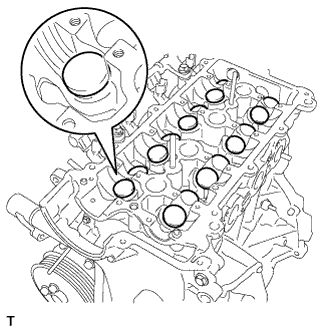
Using a micrometer, measure the thickness of the removed lifter.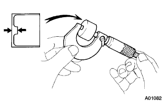
Calculate the thickness of a new lifter so that the valve clearance comes to within the specified values.
A
Thickness of new lifter
B
Thickness of used lifter
C
Measured valve clearance
- Valve clearance:
- Intake A = B + (C - 0.18 mm (0.007 in.))
- Exhaust A = B + (C - 0.25 mm (0.010 in.))
Select a new lifter with a thickness as close to the calculated values as possible.
- HINT:
- Lifters are available in 29 sizes in increments of 0.020 mm (0.0008 in.), from 5.120 mm (0.2016 in.) to 5.680 mm (0.2228 in.).
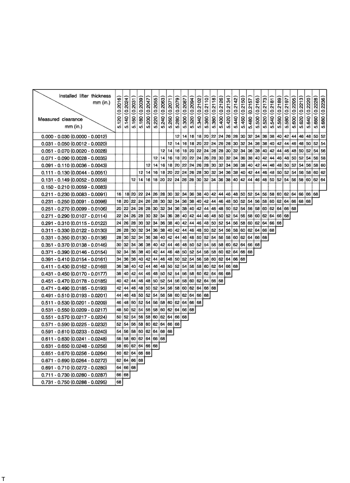
- Intake valve clearance (Cold):
- 0.145 to 0.235 mm (0.00571 to 0.00925 in.)
- EXAMPLE:
- The 5.260 mm (0.2071 in.) lifter is installed, and the measured clearance is 0.400 mm (0.0157 in.).
- Replace the 5.260 mm (0.2071 in.) lifter with a new No. 48 lifter.
- New lifter thickness:
Lifter No.
Thickness
Lifter No.
Thickness
Lifter No.
Thickness
12
5.120 (0.2016)
32
5.320 (0.2094)
52
5.520 (0.2173)
14
5.140 (0.2024)
34
5.340 (0.2102)
54
5.540 (0.2181)
16
5.160 (0.2031)
36
5.360 (0.2110)
56
5.560 (0.2189)
18
5.180 (0.2039)
38
5.380 (0.2118)
58
5.580 (0.2197)
20
5.200 (0.2047)
40
5.400 (0.2126)
60
5.600 (0.2205)
22
5.220 (0.2055)
42
5.420 (0.2134)
62
5.620 (0.2213)
24
5.240 (0.2063)
44
5.440 (0.2142)
64
5.640 (0.2220)
26
5.260 (0.2071)
46
5.460 (0.2150)
66
5.660 (0.2228)
28
5.280 (0.2079)
48
5.480 (0.2157)
68
5.680 (0.2236)
30
5.300 (0.2087)
50
5.500 (0.2165)
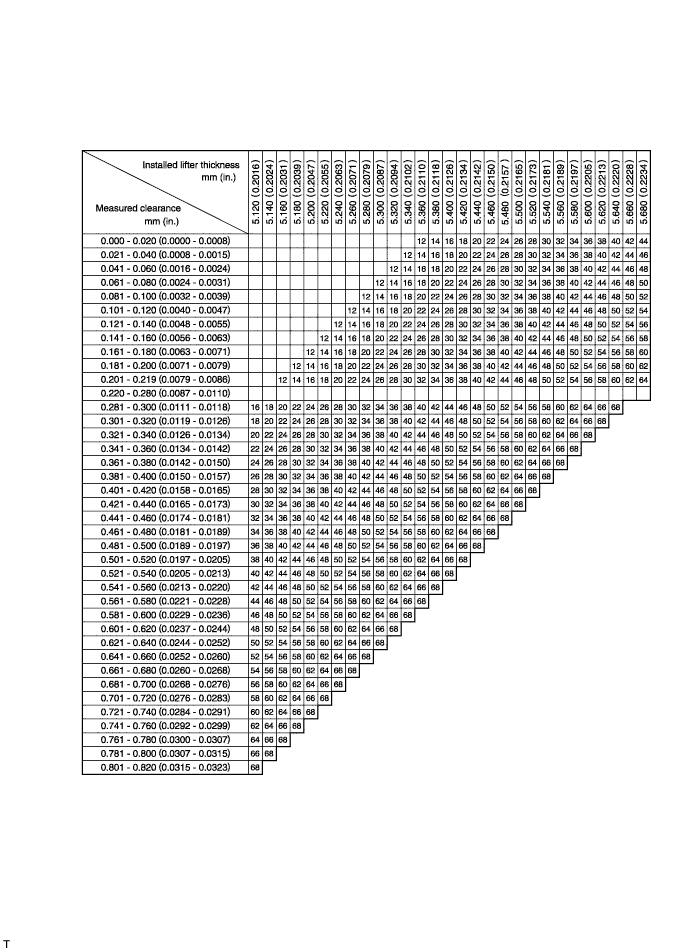
- Exhaust valve clearance (Cold):
- 0.215 to 0.305 mm (0.00492 to 0.01201 in.)
- EXAMPLE:
- The 5.300 mm (0.2087 in.) lifter is installed, and the measured clearance is 0.440 mm (0.0173 in.).
- Replace the 5.340 mm (0.2102 in.) lifter with a new No. 48 lifter.
- New lifter thickness:
Lifter No.
Thickness
Lifter No.
Thickness
Lifter No.
Thickness
12
5.120 (0.2016)
32
5.320 (0.2094)
52
5.520 (0.2173)
14
5.140 (0.2024)
34
5.340 (0.2102)
54
5.540 (0.2181)
16
5.160 (0.2031)
36
5.360 (0.2110)
56
5.560 (0.2189)
18
5.180 (0.2039)
38
5.380 (0.2118)
58
5.580 (0.2197)
20
5.200 (0.2047)
40
5.400 (0.2126)
60
5.600 (0.2205)
22
5.220 (0.2055)
42
5.420 (0.2134)
62
5.620 (0.2213)
24
5.240 (0.2063)
44
5.440 (0.2142)
64
5.640 (0.2220)
26
5.260 (0.2071)
46
5.460 (0.2150)
66
5.660 (0.2228)
28
5.280 (0.2079)
48
5.480 (0.2157)
68
5.680 (0.2236)
30
5.300 (0.2087)
50
5.500 (0.2165)
Install the selected valve lifter.
Apply new engine oil to the valve lifter and journal of the cylinder head.
Place the intake camshaft on the cylinder head so that the cam noses of cylinders No. 3 and No. 4 face as shown in the illustration.
Apply new engine oil to the lifter and journal of the cylinder head.
Place the exhaust camshaft on the cylinder head so that the cam noses of cylinders No. 2 and No. 4 face as shown in the illustration.
Install the camshaft bearing caps with the 4 bolts.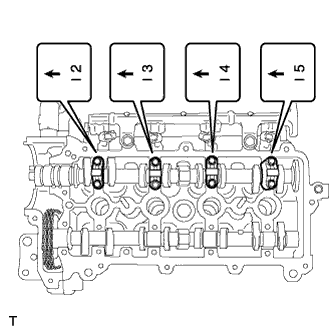
Install the camshaft bearing caps with the 4 bolts.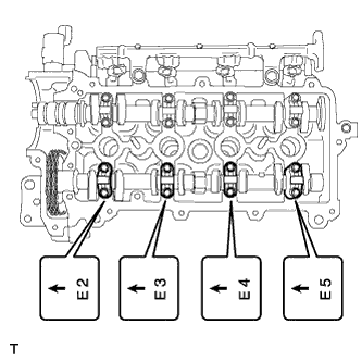
Provisionally install the camshaft bearing cap with the 4 bolts, as shown in the illustration.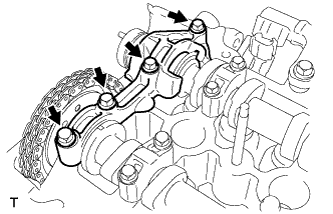
Uniformly tighten the 20 bolts in several steps in the sequence shown in the illustration.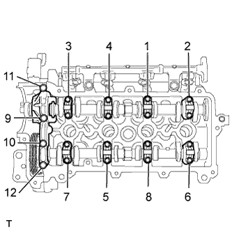
- Torque:
- 13 N*m{ 130 kgf*cm , 10 ft.*lbf }
Make sure that the marks of the camshaft timing sprocket and camshaft timing gear are in the positions shown in the illustration.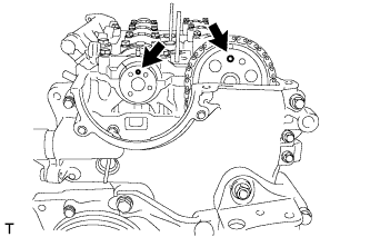
Make sure that the timing mark (cutout) of the crankshaft pulley is in the position shown in the illustration.
Align the marks of the camshaft timing sprocket and the chain and install the camshaft timing sprocket.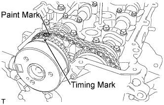
Align the knock pin of the camshaft with the pin hole in the camshaft timing sprocket and install the camshaft timing sprocket onto the camshaft.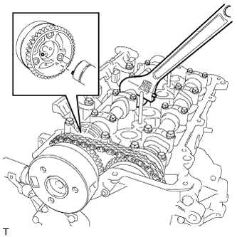
- NOTICE:
- If the knock pin and the pin hole are not aligned, using the hexagonal portion of the camshaft, slightly turn the camshaft to align them. Do not apply excessive force to the camshaft timing sprocket as the tip of the knock pin could damage the seal surface.
- If the knock pin and the pin hole are not aligned, using the hexagonal portion of the camshaft, slightly turn the camshaft to align them. Do not apply excessive force to the camshaft timing sprocket as the tip of the knock pin could damage the seal surface.
Apply a small amount of engine oil to the screw and seat surface of the camshaft timing sprocket installing bolt.
Using the hexagonal portion of the camshaft, install the camshaft timing sprocket.
- Torque:
- 47 N*m{ 480 kgf*cm , 35 ft.*lbf }
Align the marks of the camshaft timing gear and the chain and install the camshaft timing sprocket.
Align the knock pin of camshaft No. 2 with the pin hole in the camshaft timing gear and install the camshaft timing gear onto camshaft No. 2.
- HINT:
- If the knock pin and the pin hole are not aligned, using the hexagonal portion of the camshaft, slightly turn the camshaft to align them.
Provisionally tighten the bolt of camshaft No. 2 indicated by the arrow in the illustration.
Remove the 3 mm diameter bar from the chain tensioner.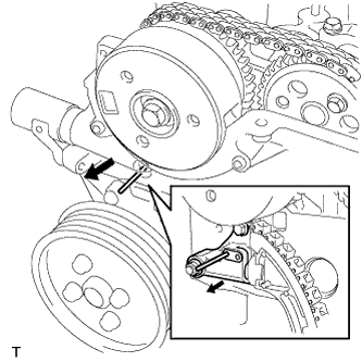
- NOTICE:
- Using the hexagonal portion of the camshaft, slightly turn the camshaft counterclockwise and remove the 3 mm diameter bar with the chain on the tensioner loose.
Make sure that the timing mark of the camshaft pulley is in the position shown in the illustration.
Make sure that the marks of the camshaft timing sprocket and camshaft timing gear are in the positions shown in the illustration.
Apply adhesive 1234 to 2 to 3 the end threads of the chain cover service hole screw plug bolt.
- NOTICE:
- Keep the bolt and the bolt hole free of oil.
Using socket hexagon wrench 10, install the chain cover service hole screw plug.
- Torque:
- 17 N*m{ 173 kgf*cm , 13 ft.*lbf }
Turn the crankshaft pulley clockwise and provisionally install the camshaft timing gear or sprocket with the 2 camshaft timing gear fixing bolts indicated by the arrows in the illustration. Then tighten it to the specified torque with the 3 bolts.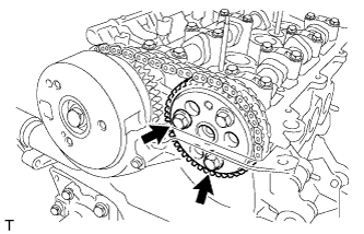
- Torque:
- 8.0 N*m{ 82 kgf*cm , 6 in.*lbf }
| 45. INSTALL CAM TIMING OIL CONTROL VALVE ASSEMBLY |
Install the cam timing oil control valve with the bolt.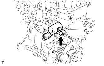
- Torque:
- 7.5 N*m{ 76 kgf*cm , 66 in.*lbf }
| 46. INSTALL CYLINDER HEAD COVER SUB-ASSEMBLY |
Apply seal packing black to the positions shown in the illustration.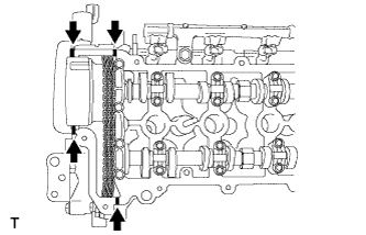
- Seal packing:
- Toyota genuine seal packing black, Three bond 12078B or Equivalent.
- NOTICE:
- Keep the installation surfaces free of oil.
- Install the installation surfaces within 3 minutes of applying seal packing.
- Do not start the engine within 2 hours of installation.
- Keep the installation surfaces free of oil.
Using several steps, tighten the 11 bolts and 2 nuts in the sequence shown in the illustration to install the cylinder head cover.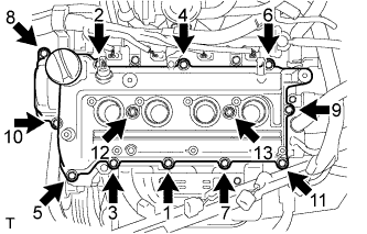
- Torque:
- 11 N*m{ 112 kgf*cm , 8 ft.*lbf }
| 47. INSTALL VENTILATION VALVE SUB-ASSEMBLY |
Install a new grommet.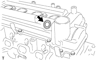
Install the ventilation valve.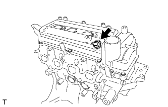
| 48. INSTALL OIL FILLER CAP SUB-ASSEMBLY |
Install a new gasket onto the oil filler cap.
Install the oil filler cap.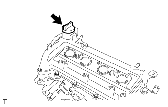
| 49. INSTALL ENGINE OIL PRESSURE SWITCH ASSEMBLY |
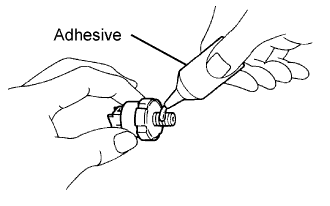 |
Apply adhesive to the 2 or 3 end threads of the oil pressure switch.
- Adhesive:
- Toyota genuine adhesive 1324, Three bond 1324 or Equivalent.
for DENSO, YAZAKI made: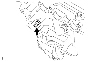
Using a 22 mm (0.8661 in.) deep socket wrench, install the oil pressure switch.
- Torque:
- 15 N*m{ 153 kgf*cm , 11 ft.*lbf }
for JAEGER made:
Using a 24 mm (0.9449 in.) deep socket wrench, install the oil pressure switch.
- Torque:
- 15 N*m{ 153 kgf*cm , 11 ft.*lbf }
| 50. INSTALL CRANKSHAFT POSITION SENSOR |
Install the crankshaft position sensor with the bolt.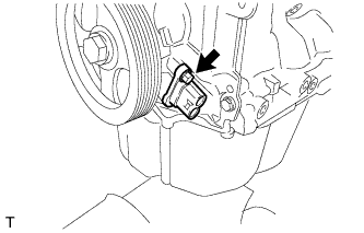
- Torque:
- 7.5 N*m{ 76 kgf*cm , 66 in.*lbf }
| 51. INSTALL CAMSHAFT POSITION SENSOR |
Install the camshaft position sensor with the bolt.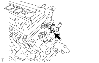
- Torque:
- 7.5 N*m{ 76 kgf*cm , 66 in.*lbf }