C1251/51 Open in Pump Motor Circuit
Diagnostic trouble codes · Vehicles built from Nov 2005
DESCRIPTION
| DTC No. |
DTC Detecting Condition |
Trouble Areas |
| C1251/51 |
When any of following conditions detected with normal battery voltage (10 V or more):
|
|
WIRING DIAGRAM
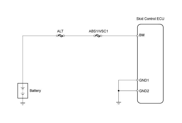

INSPECTION PROCEDURE
- NOTICE:
- When replacing the ABS and TRACTION actuator, perform zero point calibration (Click here).
| 1. PERFORM ACTIVE TEST USING INTELLIGENT TESTER |

Connect the intelligent tester to the DLC3.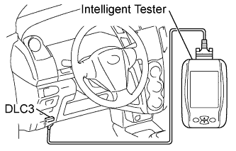
Turn the ignition switch on (IG).
Turn the tester on.
Clear the DTC (Click here).
Perform the active test using the intelligent tester.Select the following menu items: Chassis / ABS/VSC/TRC / Active Test.
Item (Display)
Vehicle Condition : Test Details
Diagnostic Note
Motor Relay
Turns ABS motor relay ON or OFF
Operating sound of motor can be heard
Check the operation sound of the ABS motor when operating it with the intelligent tester.
- OK:
- The operation sound of the ABS motor can be heard.
|
|
||||

| OK | |
 |
| 2. INSPECT FUSE (ABS1/VSC1) |
Remove the ABS1/VSC1 fuse from the engine room R/B.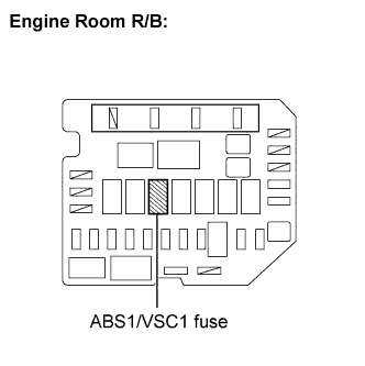
Measure the resistance.
- Standard Resistance:
- Below 1 Ω
|
|
||||

| OK | |
|
| 3. CHECK HARNESS AND CONNECTOR (BATTERY - SKID CONTROL ECU - BODY GROUND) |
Disconnect the skid control ECU connector.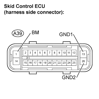
Measure the voltage.
- Standard Voltage:
Tester Connection
Specified Condition
A39-1 (BM) - Body ground
10 to 14 V
Measure the resistance.
- Standard Resistance:
Tester Connection
Specified Condition
A39-13 (GND1) - Body ground
Below 1 Ω
A39-26 (GND1) - Body ground
Below 1 Ω
|
|
||||
| OK | |
|
| 4. RECONFIRM DTC |
Clear the DTC (Click here).
Start the engine.
Check if the same DTC is output (Click here).
- Result:
Result
Proceed to
DTC output
A
DTC not output
B
|
|
||||
| A | ||
 |
||
| ||