REMOVAL
Removal / installation · Vehicles built from Jan 2006
| 1. PLACE FRONT WHEELS FACING STRAIGHT AHEAD |
| 2. DISCONNECT CABLE FROM NEGATIVE BATTERY TERMINAL |
| 3. REMOVE STEERING PAD |

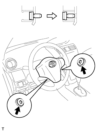  |
Using "Torx" socket wrench T30, loosen the 2 bolts completely.
Pull the steering pad toward you.
Using a thin-bladed screwdriver, release the locking button.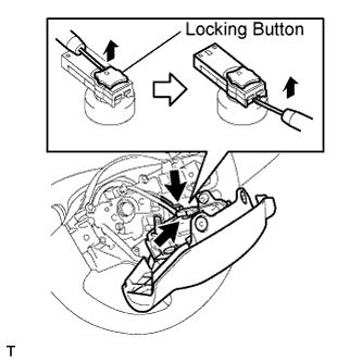
Using a thin-bladed screwdriver, disconnect the 2 connectors.
Detach the horn terminal.
| 4. REMOVE STEERING WHEEL ASSEMBLY |
Remove the nut and place matchmarks on the steering wheel assembly and steering column assembly.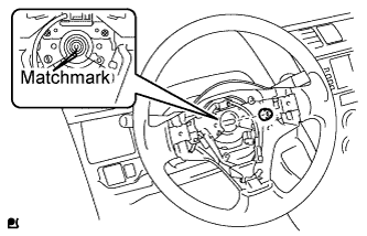
Using SST, remove the steering wheel assembly.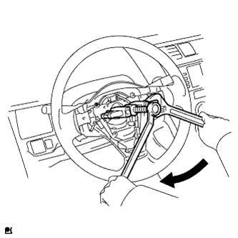
- NOTICE:
- Apply a small amount of grease to the threads and tip of the SST center bolt before using.
| 5. REMOVE STEERING COLUMN COVER |
Remove the 3 screws, disengage the 2 claws, release the tilt lever and remove the steering column lower cover.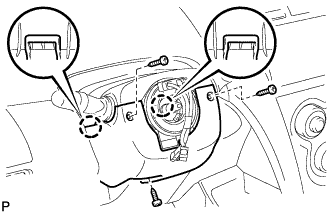
Disengage the claw and remove the steering column upper cover.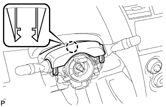
| 6. REMOVE COMBINATION SWITCH ASSEMBLY |
Disconnect all connectors from the turn signal switch with spiral cable.
Disengage the clamp indicated by the arrow in the illustration and remove the combination switch assembly from the steering column assembly.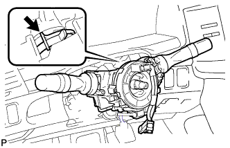
| 7. REMOVE INSTRUMENT PANEL FINISH PANEL LOWER CENTER |
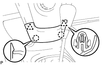 |
Disengage the 2 claws and 2 clips and remove the instrument panel finish panel lower center.
| 8. REMOVE INSTRUMENT PANEL FINISH PANEL END LH |
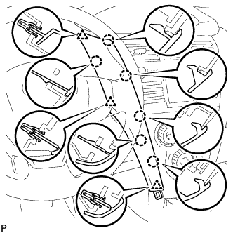 |
Disengage the 6 claws and 3 clips and remove the instrument panel finish panel end LH.
| 9. REMOVE INSTRUMENT PANEL FINISH PANEL END RH |
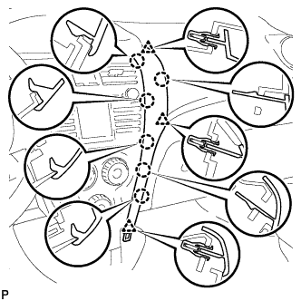 |
Disengage the 6 claws and 3 clips and remove the instrument panel finish panel end RH.
| 10. REMOVE INSTRUMENT CLUSTER FINISH PANEL |
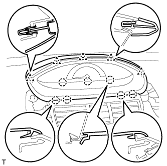 |
Disengage the 4 claws and 5 clips and remove the instrument cluster finish panel.
| 11. REMOVE COMBINATION METER ASSEMBLY |
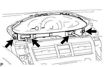 |
Disconnect the 2 connectors.
Remove the 2 screws and pull the combination meter rearward to remove it.
| 12. SEPARATE FRONT DOOR OPENING TRIM WEATHERSTRIP RH |
Separate the front door opening trim weatherstrip.
| 13. SEPARATE FRONT DOOR OPENING TRIM WEATHERSTRIP LH |
Separate the front door opening trim weatherstrip.
| 14. REMOVE FRONT PILLAR GARNISH RH |
w/ Curtain Shield Airbag: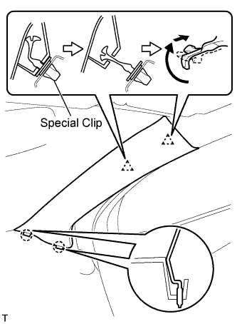
- NOTICE:
- Install a protective cover onto the curtain shield airbag as soon as the front pillar garnish is removed.
- Replace the special clip with a new one when the front pillar garnish is removed.
- Install a protective cover onto the curtain shield airbag as soon as the front pillar garnish is removed.
Disengage the 2 clips and the 2 claws and remove the front pillar garnish.
w/o Curtain Shield Airbag: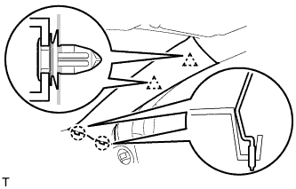
Disengage the 2 clips and the 2 claws and remove the front pillar garnish.
Disconnect the antenna connector.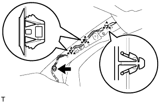
Using a clip remover, remove the 3 clamps.
w/ Curtain Shield Airbag: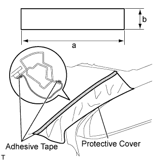
Completely cover the curtain shield airbag with a piece of cloth or nylon and fix the ends of the fabric with adhesive tape, as shown in the illustration.
- Protective cover size:
Area
Measurement
a
700 mm (27.56 in.)
b
120 mm (4.72 in.)
| 15. REMOVE FRONT PILLAR GARNISH LH |
w/ Curtain Shield Airbag: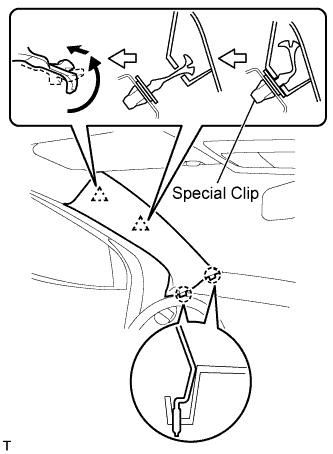
- NOTICE:
- Install a protective cover onto the curtain shield airbag as soon as the front pillar garnish is removed.
- Replace the special clip with a new one when the front pillar garnish is removed.
- Install a protective cover onto the curtain shield airbag as soon as the front pillar garnish is removed.
Disengage the 2 clips and the 2 claws and remove the front pillar garnish.
w/o Curtain Shield Airbag: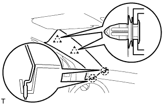
Disengage the 2 clips and the 2 claws and remove the front pillar garnish.
Using a clip remover, remove the 4 clamps.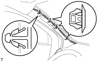
w/ Curtain Shield Airbag: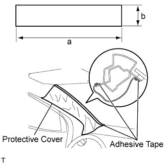
Completely cover the curtain shield airbag with a piece of cloth or nylon and fix the ends of the fabric with adhesive tape, as shown in the illustration.
- Protective cover size:
Area
Measurement
a
700 mm (27.56 in.)
b
120 mm (4.72 in.)
| 16. REMOVE GLOVE COMPARTMENT DOOR ASSEMBLY |
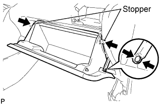 |
Disengage the claw and separate the glove compartment door stopper from the glove compartment door.
Slightly flex the upper part of the glove compartment door assembly to release the 2 stoppers and open the glove compartment door until it becomes horizontal.
Pull the glove compartment door assembly out horizontally to disengage the hinge portion and remove the glove compartment door.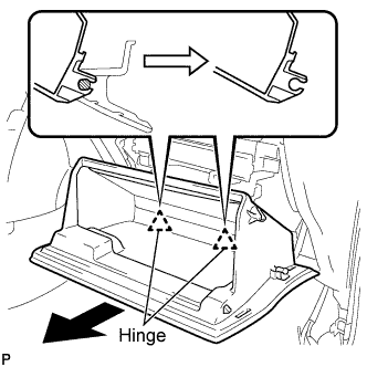
- NOTICE:
- Pull the glove compartment door out horizontally, otherwise, installation failure caused by excessive play around the hinge portion will result.
| 17. REMOVE UPPER INSTRUMENT PANEL SUB-ASSEMBLY |
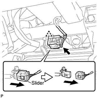 |
Slide the slider and disconnect the passenger airbag connector.
Disconnect the clamp.
Remove the 2 <C> bolts and 2 <B> screws.
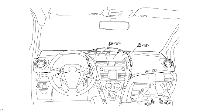
Disengage the 7 clips by lifting the rear side of the instrument panel up.
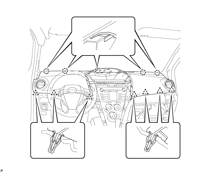
While lifting the instrument panel, slide it toward the rear of the vehicle. Disengage the 5 claws from the front side of the instrument panel and remove the instrument panel.
| 18. DISCONNECT POWER STEERING ECU |
Detach the power steering motor harness and torque sensor wire harness clamps from the power steering ECU side.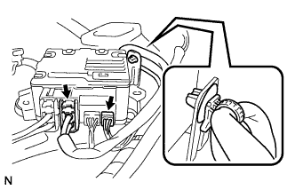
Disconnect the 2 steering column assembly connectors from the power steering ECU.
| 19. REMOVE INSTRUMENT PANEL UNDER TRAY |
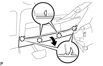 |
Disengage the 4 claws and open the instrument panel under tray.
Remove the 2 <A> screws.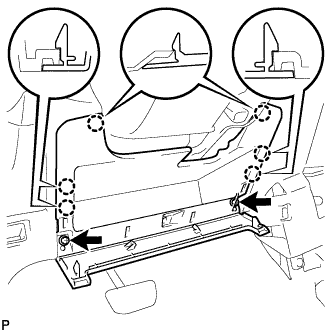
Disengage the 6 claws and remove the instrument panel under tray.
| 20. REMOVE COLUMN HOLE COVER SILENCER SHEET |
Remove the floor carpet and 2 clips and remove the column hole cover silencer.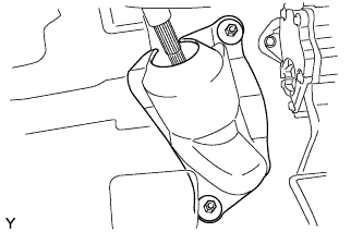
| 21. REMOVE NO.2 STEERING INTERMEDIATE SHAFT ASSEMBLY |
Loosen bolt A.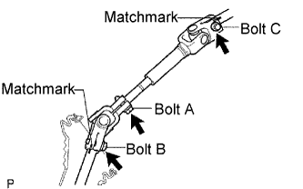
Place matchmarks on the steering intermediate assembly and steering gear assembly.
Remove bolt B and detach the steering intermediate assembly from the steering gear assembly.
Place matchmarks on the steering intermediate assembly and steering column assembly.
Remove bolt C and detach the steering intermediate shaft assembly from the steering column assembly.
| 22. REMOVE BRAKE PEDAL (for Automatic Transaxle) |
Using needle-nose pliers, remove the brake pedal return spring.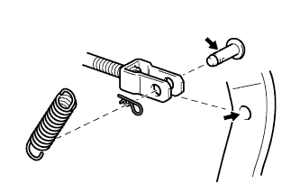
Remove the clip from the brake master cylinder push rod clevis pin.
Remove the brake master cylinder push rod clevis pin and detach the push rod clevis from the brake pedal.
Remove the bolt, nut and 2 brake pedal bushes, and remove the brake pedal assembly.
| 23. REMOVE BRAKE MASTER CYLINDER PUSH ROD CLEVIS (for Manual Transaxle) |
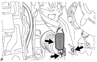 |
Remove the brake pedal return spring.
Remove the clip and the push rod pin and separate the push rod clevis from the brake pedal.
| 24. REMOVE BRAKE PEDAL SUPPORT SUB-ASSEMBLY (for Manual Transaxle) |
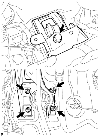 |
Remove the 4 nuts and bolt and remove the pedal support.
| 25. REMOVE STEERING COLUMN ASSEMBLY |
Disconnect all connectors and detach all wire harness clamps from the steering column assembly.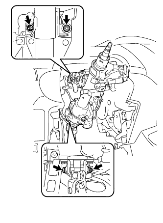
Remove the bolt and 2 nuts and remove the steering column assembly from the instrument panel reinforcement assembly.