2.
DISCONNECT CABLE FROM NEGATIVE BATTERY TERMINAL
3.
REMOVE ENGINE UNDER COVER LH
4.
REMOVE ENGINE UNDER COVER RH
5.
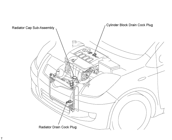
DRAIN ENGINE COOLANT
NOTICE:
To avoid the danger of being burned, do not remove the radiator cap sub-assembly while the engine and radiator assembly are still hot. Thermal expansion will cause hot engine coolant and steam to blow out from the radiator assembly.
Loosen the radiator drain cock plug.
Remove the radiator cap sub-assembly.
Loosen the cylinder block drain cock plug, then drain the coolant.
6.
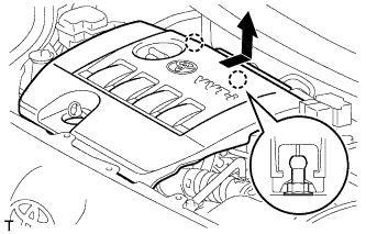
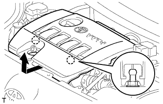
REMOVE NO. 2 CYLINDER HEAD COVER
Disengage the 2 fittings shown in the illustration.
Disengage the 2 fittings shown in the illustration, then remove the No. 2 cylinder head cover.
7.
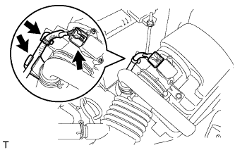
REMOVE AIR CLEANER CAP SUB-ASSEMBLY WITH HOSE
Disconnect the wire harness clamp and mass air flow meter connector.
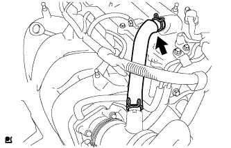
Disconnect the No. 2 ventilation hose.
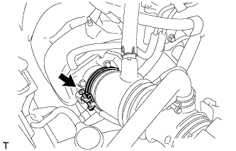
Loosen the hose clamp, unlock the 2 clamps and remove air cleaner cap sub-assembly with hose.
8.
SEPARATE ENGINE WIRE HARNESS
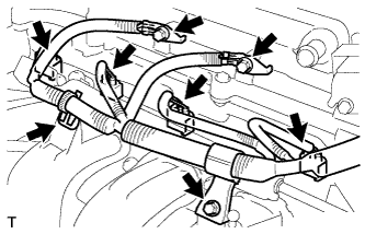
Remove the 3 bolts, harness clamp and 4 fuel injector connectors and separate the engine wire harness.
9.
REMOVE HARNESS BRACKET
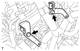
Disconnect the 4 wire harness clamps shown in the illustration.
Remove the 2 bolts and remove the 2 harness brackets.
10.
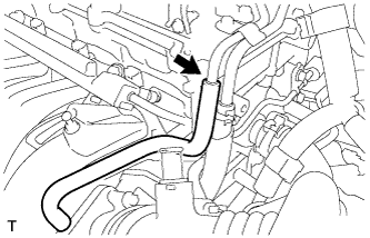
DISCONNECT NO. 1 FUEL VAPOR FEED HOSE
Disconnect the No. 1 fuel vapor feed hose.
11.
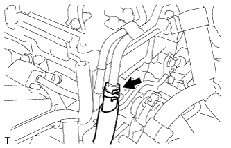
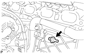
DISCONNECT VACUUM HOSE
Disconnect the vacuum hose.
12.
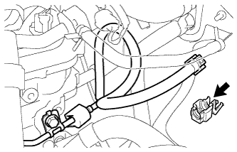
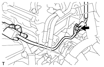
REMOVE FUEL PIPE CLAMP
Remove the fuel pipe clamp.
13.
DISCONNECT FUEL TUBE SUB-ASSEMBLY
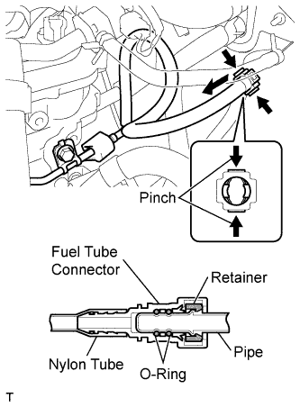
Pinch the retainer of the fuel tube connector, then pull out the fuel tube connector to disconnect the fuel tube from the fuel pipe.
NOTICE:
Remove any dirt and foreign matter from the fuel tube connector before performing this work.
Do not allow any scratches or foreign matter on the parts when disconnecting as the fuel tube connector has O-rings that seal the pipe.
Perform this work by hand. Do not use any tools.
Do not forcibly bend, twist or turn the nylon tube.
Protect the disconnected parts by covering them with vinyl bags after disconnecting the fuel tube.
If the fuel tube connector and pipe are stuck, push and pull to release them.
14.
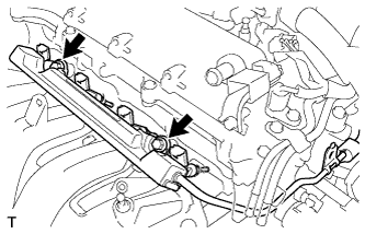
REMOVE FUEL DELIVERY PIPE SUB-ASSEMBLY
Remove the bolt.
Remove the 2 bolts and remove the fuel delivery pipe with the 4 fuel injectors.
NOTICE:
Do not drop the fuel injectors when removing the fuel delivery pipe.
15.
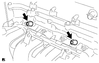
REMOVE NO. 1 DELIVERY PIPE SPACER
Remove the 2 No. 1 delivery pipe spacers.
16.
REMOVE INJECTOR VIBRATION INSULATOR
Remove the 4 injector vibration insulators.
17.
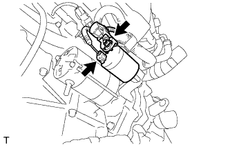
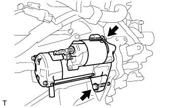
REMOVE STARTER ASSEMBLY
Remove the terminal cap.
Remove the nut and disconnect terminal 30.
Disconnect the connector.
Remove the 2 bolts and remove the starter assembly.
18.
REMOVE ENGINE OIL LEVEL DIPSTICK
19.
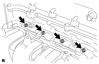
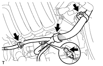
REMOVE INTAKE MANIFOLD
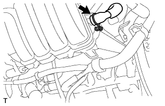
Disconnect the 4 wire harness clamps.
Disconnect the ventilation hose.
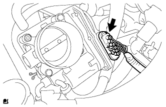
Disconnect the throttle body connector.
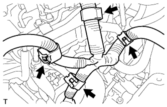
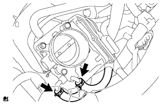
Disconnect the water by-pass hose and No. 2 water by-pass hose.
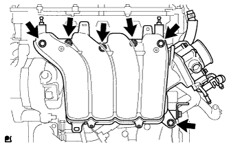
Remove the 4 bolts and 2 nuts and remove the intake manifold and intake manifold stay.