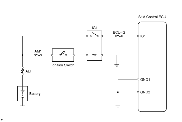
DTC C1241/41 Low Battery Positive Voltage or Abnormally High Battery Positive Voltage |
| DTC No. | DTC Detecting Conditions | Trouble Areas |
| C1241/41 | When any of following conditions detected:
|
|
| 1.CHECK SKID CONTROL ECU TERMINAL VOLTAGE |
Disconnect the skid control ECU connector.
Turn the ignition switch to ON.
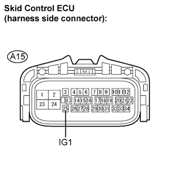 |
Measure the voltage.
| Tester Connection | Specified Condition |
| A15-25 (IG1) - Body ground | 11 to 14 V |
|
| ||||
| OK | |
 |
| 2.RECONFIRM DTC |
Clear the DTC (Click here).
Drive the vehicle at 3 km/h (2 mph) or more for several seconds.
Check if the same DTC is output (Click here).
| Result | Proceed to |
| DTC output | A |
| DTC not output | B |
|
| ||||
| A | ||
 | ||
| ||
| 3.INSPECT FUSES (ECU-IG, AM1) |
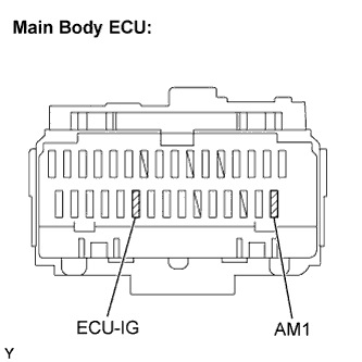 |
Remove the ECU-IG and AM1 fuses from the main body ECU.
Measure the resistance.
|
| ||||
| OK | |
|
| 4.INSPECT BATTERY |
Check the battery voltage.
|
| ||||
| OK | |
|
| 5.INSPECT IGNITION RELAY NO. 1 |
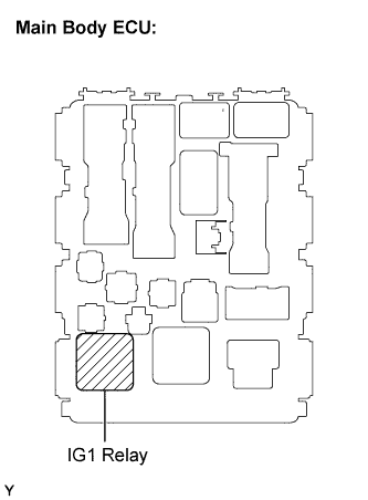 |
Remove the IG1 relay from the main body ECU.
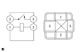 |
Measure the resistance.
| Tester Connection | Condition | Specified Condition |
| 3 - 5 | Always | 10 kΩ or higher |
| 3 - 5 | Apply B+ between terminals 1 and 2 | Below 1 Ω |
|
| ||||
| OK | |
|
| 6.CHECK HARNESS AND CONNECTOR (SKID CONTROL ECU - BODY GROUND) |
Inspect the skid control ECU connector fitting for defects.
Disconnect the skid control ECU connector.
Inspect both the connector case and the terminal for deformation and corrosion.
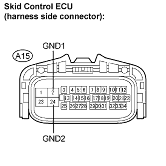 |
Measure the resistance.
| Tester Connection | Specified Condition |
| A15-2 (GND1) - Body ground | Below 1 Ω |
| A15-24 (GND2) - Body ground | Below 1 Ω |
|
| ||||
| OK | ||
| ||
| ||

