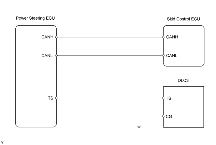
ANTI-LOCK BRAKE SYSTEM (for Sedan) > TS and CG Terminal Circuit |
| 1.CHECK HARNESS AND CONNECTOR (DLC3 - POWER STEERING ECU) |
Turn the ignition switch off.
Disconnect the power steering ECU connector.
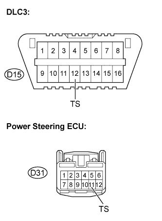 |
Measure the resistance.
| Tester Connection | Specified Condition |
| D15-12 (TS) - D31-11 (TS) | Below 1 Ω |
|
| ||||
| OK | |
 |
| 2.CHECK HARNESS AND CONNECTOR (DLC3 - BODY GROUND) |
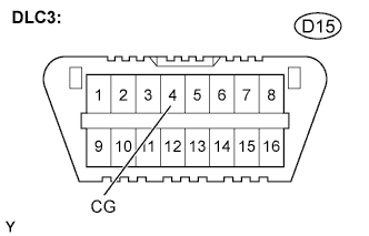 |
Measure the resistance.
| Tester Connection | Specified Condition |
| D15-4 (CG) - Body ground | Below 1 Ω |
|
| ||||
| OK | |
|
| 3.CHECK HARNESS AND CONNECTOR (POWER STEERING ECU - BODY GROUND) |
Disconnect the power steering ECU connector.
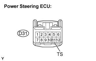 |
Measure the resistance.
| Tester Connection | Specified Condition |
| D31-11 (TS) - Body ground | 10 kΩ or higher |
|
| ||||
| OK | |
|
| 4.REPLACE POWER STEERING ECU |
Replace the power steering ECU.
Check for DTCs of the power steering ECU (Click here).
| Result | Proceed to |
| DTC not output | A |
| DTC output | B |
|
| ||||
| A | ||
 | ||
| ||
