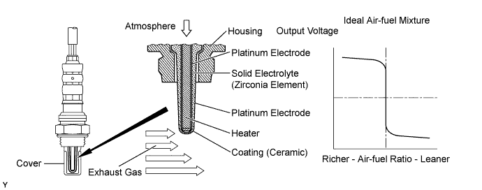
DTC P0031 Oxygen Sensor Heater Control Circuit Low (Bank 1 Sensor 1) |
DTC P0032 Oxygen Sensor Heater Control Circuit High (Bank 1 Sensor 1) |
DTC P0037 Oxygen Sensor Heater Control Circuit Low (Bank 1 Sensor 2) |
DTC P0038 Oxygen Sensor Heater Control Circuit High (Bank 1 Sensor 2) |
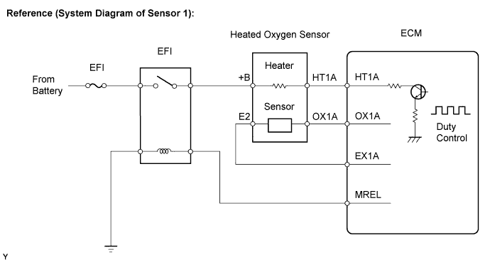
| DTC No. | DTC Detection Conditions | Trouble Areas |
| P0031 P0037 | Heated Oxygen (HO2) sensor heater current below 0.25 A when heater operates with +B greater than 10.5 V (1 trip detection logic) |
|
| P0032 P0038 | HO2 sensor heater current exceeds 2 A when heater operates (1 trip detection logic) |
|
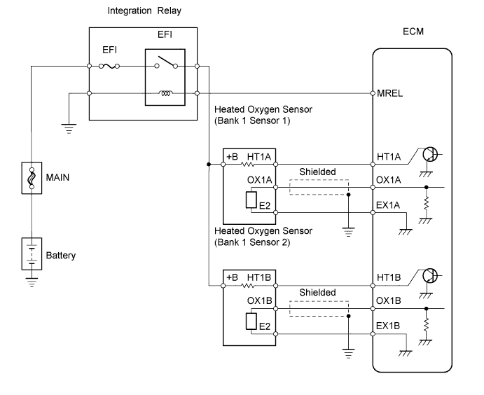
| 1.INSPECT HEATED OXYGEN SENSOR (HEATER RESISTANCE) |
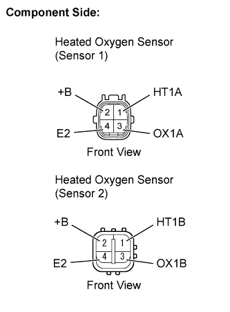 |
Disconnect the C36 or D28 Heated Oxygen (HO2) sensor connector.
Measure the resistance between the terminals of the HO2 sensor connector.
| Tester Connections | Specified Conditions |
| HT1A (1) - +B (2) | 5.3 to 7.5 Ω at 20°C (68°F) |
| HT1A (1) - E2 (4) | 10 kΩ or higher |
| Tester Connections | Specified Conditions |
| HT1B (1) - +B (2) | 11 to 16 Ω at 20°C (68°F) |
| HT1B (1) - E2 (4) | 10 kΩ or higher |
Reconnect the HO2 sensor connectors.
|
| ||||
| OK | |
 |
| 2.CHECK TERMINAL VOLTAGE (+B OF HO2 SENSOR) |
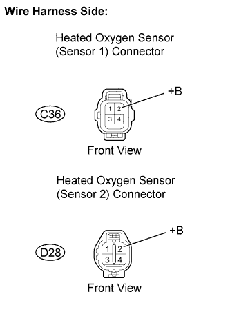 |
Disconnect the C36 or D28 HO2 sensor connector.
Turn the ignition switch to ON.
Measure the voltage between the terminals of the C36 or D28 HO2 sensor connector and the body ground.
| Tester Connections | Specified Conditions |
| +B (C36-2) - Body ground | 9 to 14 V |
| +B (D28-2) - Body ground |
Reconnect the HO2 sensor connector.
|
| ||||
| NG | |
|
| 3.INSPECT INTEGRATION NO.1 RELAY (EFI RELAY) |
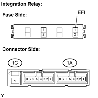 |
Remove the integration relay from the engine room relay block.
Inspect the EFI fuse.
Remove the EFI fuse from the integration relay.
Check the EFI fuse resistance.
Reinstall the EFI fuse.
Inspect the EFI relay.
Check the EFI relay resistance.
| Tester Connections | Specified Conditions |
| 1C-1 - 1A-4 | 10 kΩ or higher |
| Below 1 Ω (Apply battery voltage between terminals 1A-2 and 1A-3) |
Reinstall the integration relay.
|
| ||||
| OK | |
|
| 4.CHECK HARNESS AND CONNECTOR (HO2 SENSOR - EFI RELAY) |
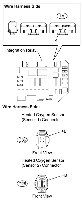 |
Disconnect the C36 or D28 HO2 sensor connector.
Remove the integration relay from the engine room relay block.
Check the resistance.
| Tester Connections | Specified Conditions |
| +B (C36-2) - Engine room relay block (1A-4) | Below 1 Ω |
| +B (D28-2) - Engine room relay block (1A-4) |
| Tester Connections | Specified Conditions |
| +B (C36-2) or Engine room relay block (1A-4) - Body ground | 10 kΩ or higher |
| +B (D28-2) or Engine room relay block (1A-4) - Body ground |
Reconnect the HO2 sensor connector.
Reinstall the integration relay.
|
| ||||
| OK | ||
 | ||
| ||
| 5.CHECK HARNESS AND CONNECTOR (HO2 SENSOR - ECM) |
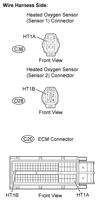 |
Disconnect the C36 or D28 HO2 sensor connector.
Disconnect the C20 ECM connector.
Check the resistance.
| Tester Connections | Specified Conditions |
| HT1A (C36-1) - HT1A (C20-109) | Below 1 Ω |
| HT1B (D28-1) - HT1B (C20-47) |
| Tester Connections | Specified Conditions |
| HT1A (C36-1) or HT1A (C20-109) - Body ground | 10 kΩ or higher |
| HT1B (D28-1) or HT1B (C20-47) - Body ground |
Reconnect the HO2 sensor connector.
Reconnect the ECM connector.
|
| ||||
| OK | |
|
| 6.CHECK WHETHER DTC OUTPUT RECURS (DTC P0031, P0032, P0037 OR P0038) |
Connect an intelligent tester to the DLC3.
Turn the ignition switch to ON and turn the tester on.
Clear DTCs (Click here).
Start the engine.
Allow the engine to idle for 1 minute or more.
Select the following menu items: Powertrain / Engine and ECT / DTC.
Read DTCs.
| Display (DTC Output) | Proceed To |
| No output | A |
| P0031, P0032, P0037 or P0038 | B |
|
| ||||
| A | ||
| ||
| ||

