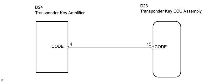
DTC B2797 Communication Malfunction No. 1 |
| DTC No. | DTC Detection Condition | Trouble Area |
| B2797 | Keys are positioned too close to each other, or noise occurred in communication line |
|
| 1.CHECK KEYS |
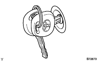 |
Check if the ignition key being used is near other ignition keys, as shown in the illustration. Also, check if the key ring is in contact with the key grip.
| Result | Proceed to |
| Key is near other keys and/or key ring is in contact with key grip. | A |
| Key is not near other keys and/or key ring is not in contact with key grip. | B |
|
| ||||
| A | |
 |
| 2.CHECK DTC |
Separate the keys from each other and/or remove the key ring.
Clear the DTC (Click here).
Insert a key into the ignition cylinder. Remove it. Repeat for all other keys.
Check that no DTC is output.
|
| ||||
| OK | ||
 | ||
| ||
| 3.CHECK TRANSPONDER KEY ECU ASSEMBLY |
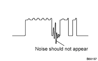 |
Using an oscilloscope or the intelligent tester, check for noise in the waveform between the terminals of the D24 amplifier connector and D23 ECU connector.
| Tester Connection | Specified Condition |
| D23-15 (CODE) - D24-4 (CODE) | No noise is present |
| Tool Setting | 5 V/DIV., 20 ms/DIV. |
| Condition | Ignition switch OFF → ON |
|
| ||||
| OK | |
|
| 4.CHECK HARNESS AND CONNECTOR (TRANSPONDER KEY ECU - TRANSPONDER KEY AMPLIFIER) |
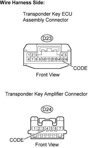 |
Disconnect the D23 transponder key ECU connector.
Disconnect the D24 transponder key amplifier connector.
Measure the resistance of the wire harness side connectors.
| Tester Connection | Specified Condition |
| D23-15 (CODE) - D24-4 (CODE) | Below 1 Ω |
Reconnect the transponder key ECU and transponder key amplifier connectors.
|
| ||||
| OK | |
|
| 5.REPLACE TRANSPONDER KEY AMPLIFIER |
After replacing the transponder key amplifier with a normally functioning amplifier, check that the engine starts.
|
| ||||
| OK | ||
| ||
| ||

