FRONT SHOCK ABSORBER WITH COIL SPRING (for Hatchback) > INSTALLATION |
| 1. TEMPORARILY TIGHTEN FRONT SHOCK ABSORBER WITH COIL SPRING |
|
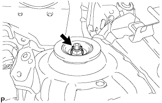
Provisionally tighten a new nut through No. 2 suspension support.
Install the front shock absorber with coil spring onto the steering knuckle.
Install the 2 bolts and 2 nuts.
| 2. INSTALL FRONT FLEXIBLE HOSE (w/ ABS) |
Install the flexible hose and speed sensor with the bolt.
| 3. INSTALL FRONT FLEXIBLE HOSE (w/o ABS) |
Install the flexible hose with the bolt.
| 4. INSTALL FRONT STABILIZER LINK ASSEMBLY |
Install the stabilizer link with the nut.
| 5. INSTALL FRONT WHEEL |
| 6. FULLY TIGHTEN FRONT SHOCK ABSORBER WITH COIL SPRING |
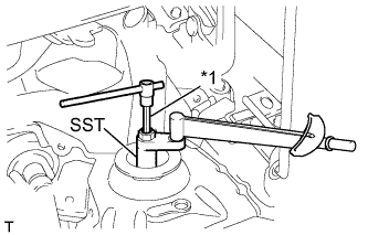 |
Using SST and a long socket hexagon wrench 6, fix the shock absorber rod and tighten the nut.
| *1 | Long Socket Hexagon Wrench 6 |
| 7. INSTALL FRONT SUSPENSION SUPPORT DUST COVER |
| 8. INSTALL COWL TOP PANEL OUTER |
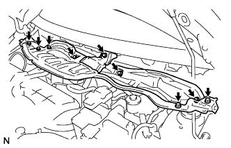 |
Install the cowl top panel with the 9 bolts.
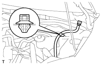 |
Connect the wire harness clamp.
| 9. INSTALL COWL TO REGISTER DUCT SUB-ASSEMBLY NO. 2 |
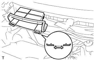 |
Engage the claw to install cowl to register duct No. 2.
| 10. INSTALL FRONT WIPER MOTOR AND LINK |
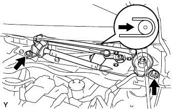 |
Connect the connector.
Slide the wiper link as shown in the illustration and engage the rubber pin with the body.
Install the front wiper motor and link with the 2 bolts.
| 11. INSTALL COWL TOP VENTILATOR LOUVER LH (for LHD) |
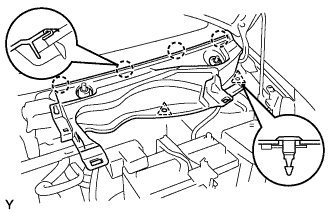 |
Engage the 4 claws and install the cowl top ventilator louver LH.
Install the 2 clips.
| 12. INSTALL COWL TOP VENTILATOR LOUVER SUB-ASSEMBLY (for LHD) |
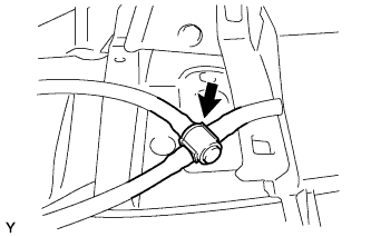 |
Connect the washer hose.
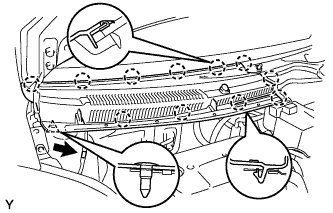 |
Engage the 11 claws and install the cowl top ventilator louver sub-assembly.
Install the clip.
Connect the washer hose.
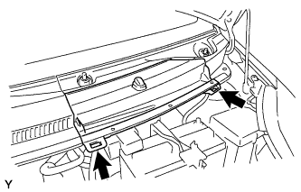 |
Engage the 2 hooks and install cowl top ventilator louver center No. 1.
| 13. INSTALL COWL TOP VENTILATOR LOUVER LH (for RHD) |
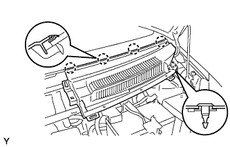 |
Engage the 4 claws and install the cowl top ventilator louver LH.
Install the clip.
| 14. INSTALL COWL TOP VENTILATOR LOUVER SUB-ASSEMBLY (for RHD) |
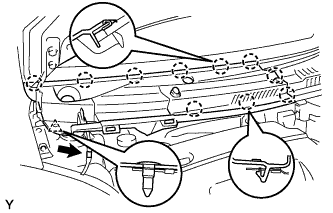 |
Engage the 10 claws and install the cowl top ventilator louver sub-assembly.
Install the clip.
Connect the washer hose.
| 15. INSTALL HOOD TO COWL TOP SEAL |
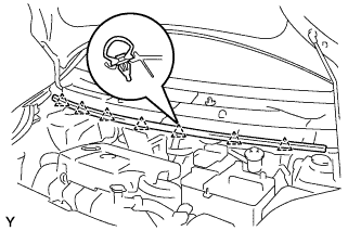 |
Engage the 7 clips and install the hood to cowl top seal.
| 16. INSTALL FRONT WIPER ARM AND BLADE ASSEMBLY LH |
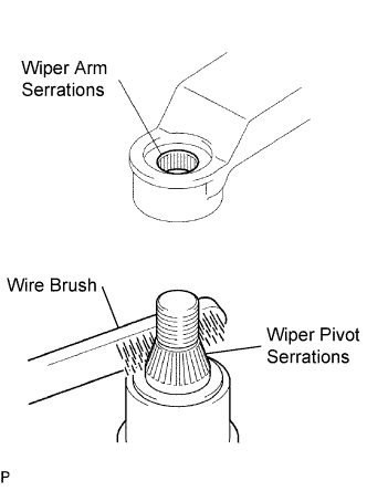 |
Scrape any metal powder off the serrated part of the wiper arm with a round file or the equivalent (when reinstalling).
Clean the wiper pivot serrations with a wire brush.
Operate the wiper, then stop the windshield wiper motor in the automatic stop position.
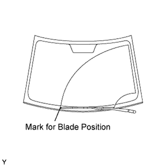 |
Align the blade tip with the mark on the windshield glass, as shown in the illustration.
Tighten the nut of the front wiper arm.
| 17. INSTALL FRONT WIPER ARM AND BLADE ASSEMBLY RH |
|
Scrape any metal powder off the serrated part of the wiper arm with a round file or the equivalent (when reinstalling).
Clean the wiper pivot serrations with a wire brush.
Operate the wiper, then stop the windshield wiper motor in the automatic stop position.
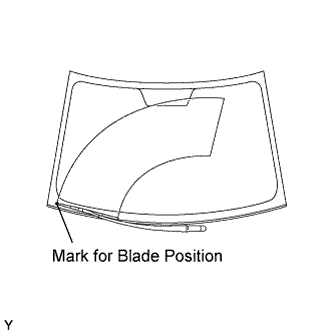 |
Align the blade tip with the mark on the windshield glass, as shown in the illustration.
Tighten the nut of the front wiper arm.
| 18. INSTALL FRONT WIPER ARM HEAD CAP |
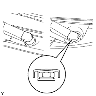 |
Engage the claw and install the 2 front wiper arm head caps.
| 19. INSPECT AND ADJUST FRONT WHEEL ALIGNMENT |