UPPER INSTRUMENT PANEL (for Hatchback) > INSTALLATION |
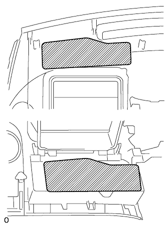
| 1. INSTALL NO. 3 INSTRUMENT PANEL CUSHION |
|
Install the 2 instrument panel cushions onto the instrument panel upper.
| 2. INSTALL NO. 2 INSTRUMENT PANEL CUSHION |
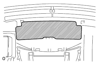 |
Install the instrument panel cushion onto the instrument panel upper.
| 3. INSTALL NO. 1 INSTRUMENT PANEL CUSHION |
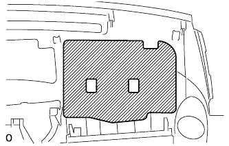 |
Install the instrument panel cushion onto the instrument panel upper.
| 4. INSTALL INSTRUMENT PANEL CUSHION |
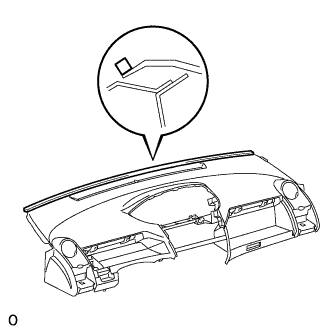 |
Install the instrument panel cushion onto the instrument panel upper.
| 5. INSTALL FRONT PASSENGER AIRBAG ASSEMBLY |
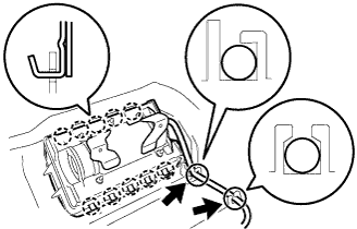 |
Engage the 10 hooks so that the connector side faces the outside of the vehicle, and install the instrument panel passenger airbag.
Install the wire harness onto the 2 claws of the instrument panel.
| 6. INSTALL NO. 1 INSTRUMENT PANEL REGISTER ASSEMBLY |
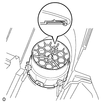 |
Engage the 3 claws and install the register.
| 7. INSTALL NO. 1 HEATER TO REGISTER DUCT |
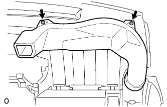 |
Install the register duct No. 1 with the 2 <A> screws.
| 8. INSTALL NO. 2 HEATER TO REGISTER DUCT |
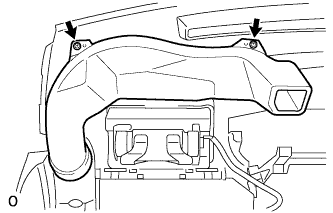 |
Install the register duct No. 2 with the 2 <A> screws.
| 9. INSTALL NO. 1 INSTRUMENT PANEL CUP HOLDER |
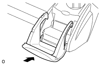 |
Engage the hinge portion of the cup holder and install the cup holder.
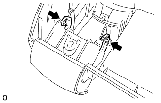 |
Engage the stopper of the cup holder.
| 10. INSTALL NO. 2 INSTRUMENT PANEL CUP HOLDER |
| 11. INSTALL INSTRUMENT PANEL CUP HOLDER SPRING |
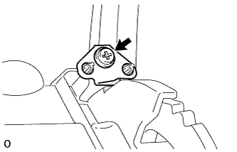 |
Install the cup holder spring with screw <A>.
| 12. INSTALL NO. 2 INSTRUMENT PANEL BOX DOOR SUB-ASSEMBLY |
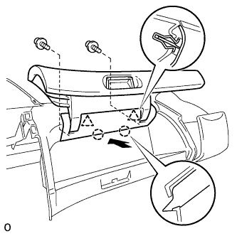 |
Engage the 2 claws and 2 clips.
Instal the box door with the 2 <A> screws.
| 13. INSTALL NO. 1 INSTRUMENT PANEL BOX DOOR SUB-ASSEMBLY |
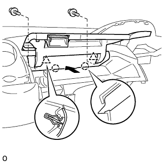 |
Engage the 2 claws and 2 clips.
Install the box door with the 2 <A> screws.
| 14. INSTALL UPPER INSTRUMENT PANEL SUB-ASSEMBLY |
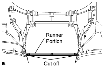 |
Using a nipper, cut off both ends of the runner portion shown in the illustration (When installing a new one).
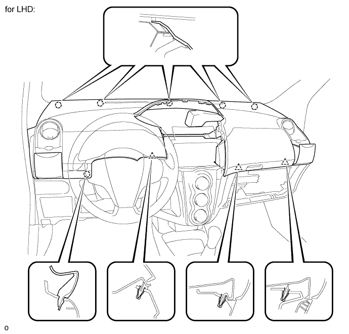
Engage the 5 claws at the upper side of the instrument panel.
Engage the claw and the 3 clips at the lower side of the instrument panel.
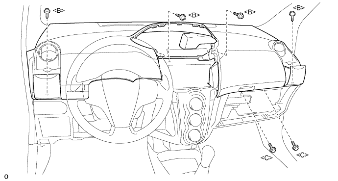
Install the instrument panel upper with the 2 <C> bolts and the 4 <B> screws.
Connect the connectors.
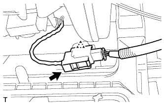 |
Connect the passenger airbag connector and clamp.
| 15. INSTALL GLOVE COMPARTMENT DOOR ASSEMBLY |
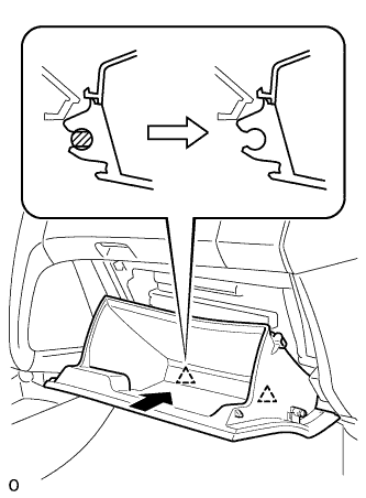 |
Engage the claw of the hinge portion in the horizontal direction to install the glove compartment door assembly.
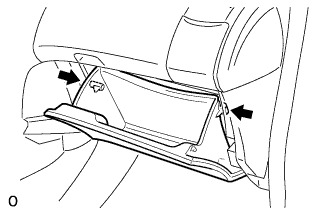 |
Slightly deform the upper portion of the glove compartment door assembly to engage the stopper.
| 16. INSTALL NO. 1 SWITCH HOLE BASE |
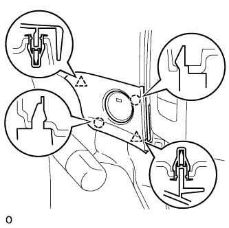 |
Disengage the 2 clips and 2 claws and install the switch hole base.
| 17. INSTALL FRONT PILLAR GARNISH RH |
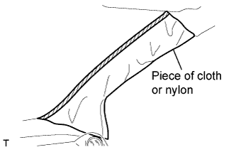 |
w/ Curtain Shield Airbag:
Remove the piece of cloth or nylon.
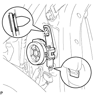 |
w/ Front No. 2 Speaker:
Insert the hook into the body hole.
Engage the clip and install the front speaker.
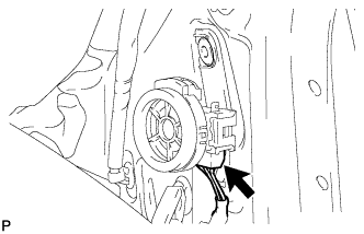 |
Connect the speaker connector.
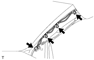 |
Install the 3 antenna cord clamps.
Connect the connector.
w/ Curtain Shield Airbag:
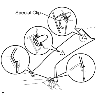 |
Install a new special clip and the clip onto a new front pillar garnish.
Engage the 2 clips and the 2 claws and install the front pillar garnish.
w/o Curtain Shield Airbag:
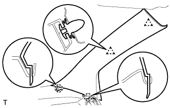 |
Engage the 2 clips and the 2 claws and install the front pillar garnish.
| 18. INSTALL FRONT PILLAR GARNISH LH |
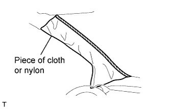 |
w/ Curtain Shield Airbag:
Remove the piece of cloth or nylon.
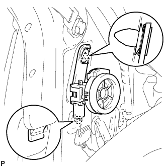 |
w/ Front No. 2 Speaker:
Insert the hook into the body hole.
Engage the clip and install the front speaker.
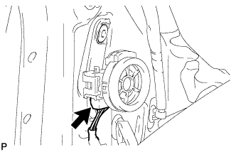 |
Connect the speaker connector.
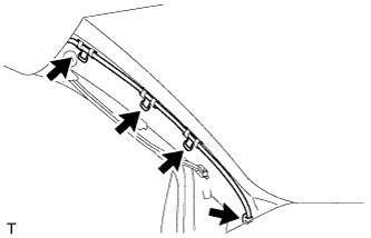 |
Install the 4 wire harness clamps.
w/ Curtain Shield Airbag:
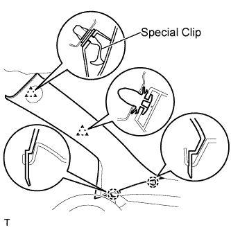 |
Install a new special clip and the clip onto a new front pillar garnish.
Engage the 2 clips and the 2 claws and install the front pillar garnish.
w/o Curtain Shield Airbag:
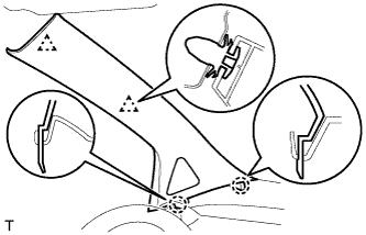 |
Engage the 2 clips and the 2 claws and install the front pillar garnish.
| 19. INSTALL FRONT DOOR OPENING TRIM WEATHERSTRIP RH |
Install the front door opening trim weatherstrip.
| 20. INSTALL FRONT DOOR OPENING TRIM WEATHERSTRIP LH |
Install the front door opening trim weatherstrip.
| 21. INSTALL COMBINATION METER ASSEMBLY |
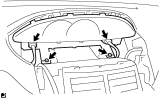 |
Install the combination meter assembly with the 2 screws.
Connect the 2 connectors.
| 22. INSTALL INSTRUMENT CLUSTER FINISH PANEL NO.1 |
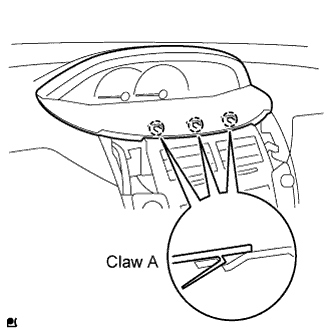 |
Fit the 3 A claws of the instrument cluster finish panel into the upper instrument cluster finish panel center.
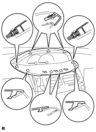 |
Engage the 4 claws and 5 clips and install the instrument cluster finish panel.
| 23. INSTALL INSTRUMENT PANEL FINISH PANEL END RH |
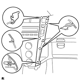 |
with CD player
Connect the connector.
Engage the 4 claws and 3 clips and install the instrument panel finish panel end RH.
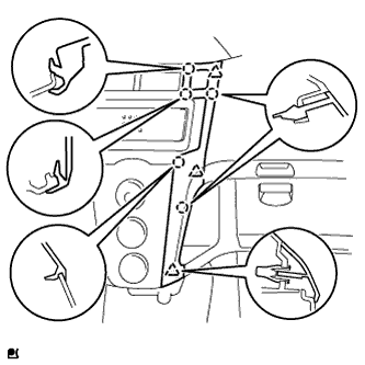 |
Except CD player
Connect the connector.
Engage the 5 claws and 3 clips and install the instrument panel finish panel end RH.
| 24. INSTALL INSTRUMENT PANEL FINISH PANEL END LH |
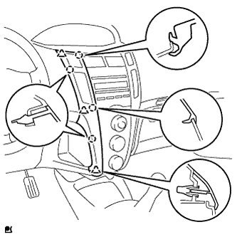 |
with CD player
Connect the connector.
Engage the 4 claws and 3 clips and install the instrument panel finish panel end LH.
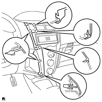 |
Except CD player
Connect the connector.
Engage the 5 claws and 3 clips and install the instrument panel finish panel end LH.
| 25. CONNECT CABLE TO NEGATIVE BATTERY TERMINAL |
| 26. CHECK SRS WARNING LIGHT |