 |
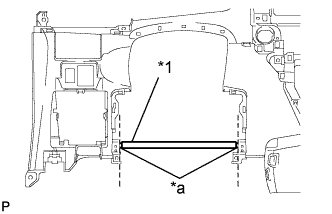
Using a nipper, cut off both ends of the runner portion shown in the illustration (When installing a new one).
| *1 | Runner Portion |
| *a | Cut Off |
LOWER INSTRUMENT PANEL (for Sedan) > INSTALLATION |
| 1. INSTALL INSTRUMENT PANEL NO. 1 SAFETY PAD |
Apply butyl tape to install the instrument panel safety pad No. 1 onto the instrument panel lower (When installing a new one).
| 2. INSTALL INSTRUMENT PANEL NO. 2 SAFETY PAD |
Apply butyl tape to install the instrument panel safety pad No. 2 onto the instrument panel lower (When installing a new one).
| 3. INSTALL INSTRUMENT CLUSTER FINISH PANEL SEAL |
Engage the 5 claws and install the panel seal.
| 4. INSTALL INSTRUMENT PANEL HOLE COVER |
Install the instrument panel hole cover with the 2 <H> screws.
| 5. INSTALL STEREO JACK ADAPTER ASSEMBLY |
Engage the 2 claws and install the stereo jack adapter.
| 6. INSTALL HEADLIGHT LEVELING SWITCH |
Engage the 2 claws and install the headlight leveling switch.
| 7. INSTALL OUTER MIRROR SWITCH ASSEMBLY |
Engage the 2 claws and install the outer mirror switch.
| 8. INSTALL GLOVE COMPARTMENT DOOR STOPPER SUB-ASSEMBLY |
Engage the claw and install the glove compartment door stopper.
| 9. INSTALL INSTRUMENT PANEL CUP HOLDER SUB-ASSEMBLY LH |
Install the instrument panel cup holder with the 3 <A> screws.
| 10. INSTALL INSTRUMENT PANEL CUP HOLDER SUB-ASSEMBLY RH |
Install the instrument panel cup holder with the 3 <A> screws.
| 11. INSTALL LOWER INSTRUMENT PANEL SUB-ASSEMBLY |
|
Using a nipper, cut off both ends of the runner portion shown in the illustration (When installing a new one).
| *1 | Runner Portion |
| *a | Cut Off |
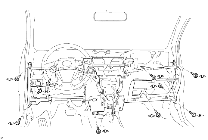
Install the lower instrument panel with the 6 <D> bolts, 2 <E> bolts, screw <G> and screw <H>.
Connect the clamps and connectors.
Engage the 2 claws and connect the DLC3 connector.
| 12. CONNECT HOOD LOCK CONTROL LEVER SUB-ASSEMBLY |
Engage the 3 claws to connect the control lever.
| 13. CONNECT ANTENNA CORD SUB-ASSEMBLY |
for LHD:
Connect the 5 antenna cord clamps.
for RHD:
Connect the 4 antenna cord clamps.
| 14. INSTALL INSTRUMENT PANEL BOX |
Insert the stopper of the instrument panel box from the cutout of the instrument panel lower.
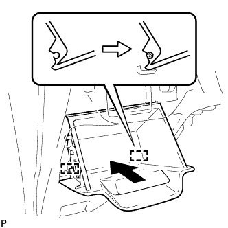 |
Engage the 2 hinges with the instrument panel open.
Close the instrument panel box.
| 15. INSTALL INSTRUMENT PANEL UNDER TRAY |
Engage the 6 claws and install the instrument panel under tray.
Install the 2 <A> screws.
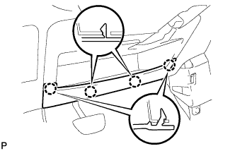 |
Engage the 4 claws and install the instrument panel under tray.
| 16. INSTALL INSTRUMENT PAD LOWER RH |
Engage the claw and 3 clips and install the instrument pad lower.
Install screw <I>.
| 17. INSTALL INSTRUMENT PAD LOWER LH |
Engage the claw and 3 clips and install the instrument pad lower.
Install screw <I>.
| 18. INSTALL REAR CONSOLE BOX ASSEMBLY |
| 19. INSTALL COWL SIDE TRIM BOARD RH |
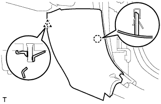 |
Engage the stud bolt and the claw and install the cowl side trim board.
| 20. INSTALL COWL SIDE TRIM BOARD LH |
| 21. INSTALL FRONT DOOR SCUFF PLATE RH |
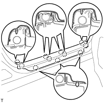 |
Engage the 11 claws and install the front door scuff plate.
| 22. INSTALL FRONT DOOR SCUFF PLATE LH |
| 23. CONNECT AIR INLET DAMPER CONTROL CABLE SUB-ASSEMBLY |
Engage the 2 claws and connect the air inlet damper control cable.
| 24. CONNECT DEFROSTER DAMPER CONTROL CABLE SUB-ASSEMBLY |
Engage the 2 claws and connect the defroster damper control cable.
| 25. CONNECT AIR MIX DAMPER CONTROL CABLE SUB-ASSEMBLY |
Engage the 2 claws and connect the air mix damper control cable.
Connect the air mix damper control cable to the clamp.
| 26. INSTALL AIR CONDITIONING PANEL ASSEMBLY |
Connect the 3 connectors and the 4 clamps.
Engage the 4 clips and 2 claws and install the air conditioning panel.
| 27. INSTALL STEREO OPENING COVER (w/o Radio Receiver) |
Install the stereo opening cover with the 4 screws.
| 28. INSTALL RADIO RECEIVER ASSEMBLY (for Integrated with Panel) |
Connect the plug.
Connect the 3 radio connectors.
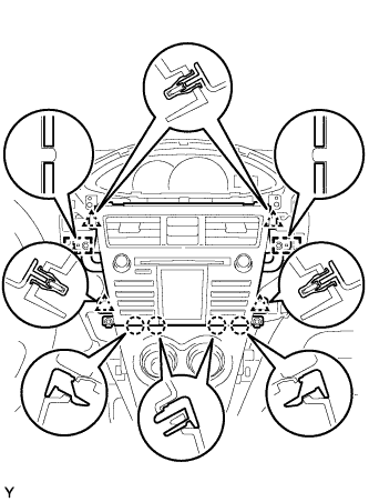 |
Align the 2 bosses of the instrument panel with the hole in the radio bracket.
Engage the 4 clips and 4 claws and install the radio receiver.
Tighten the 4 bolts.
Connect the hazard warning signal switch connector.
| 29. INSTALL RADIO RECEIVER ASSEMBLY (except Integrated with Panel) |
Connect the plug.
Connect the 2 radio connectors.
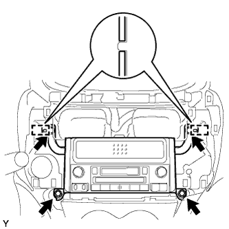 |
Align the 2 bosses of the instrument panel with the hole in the radio bracket.
Install the radio receiver with the 4 bolts.
| 30. INSTALL INSTRUMENT CLUSTER FINISH PANEL CENTER SUB-ASSEMBLY (except Integrated with Panel) |
Engage the 2 claws and 4 clips and install the instrument cluster finish panel center.
| 31. INSTALL UPPER INSTRUMENT PANEL SUB-ASSEMBLY |
| 32. INSTALL INSTRUMENT PANEL CUP HOLDER SPRING RH |
Install the spring.
| 33. INSTALL INSTRUMENT PANEL CUP HOLDER RH |
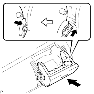 |
Install the 2 hinges of the cup holder one at a time.
Engage the spring with the instrument panel cup holder.
Flex both sides of the cup holder and engage the 2 stoppers.
Close the instrument panel cup holder.
Remove protective tape.
| 34. INSTALL INSTRUMENT PANEL CUP HOLDER SPRING LH |
Install the spring.
| 35. INSTALL INSTRUMENT PANEL CUP HOLDER LH |
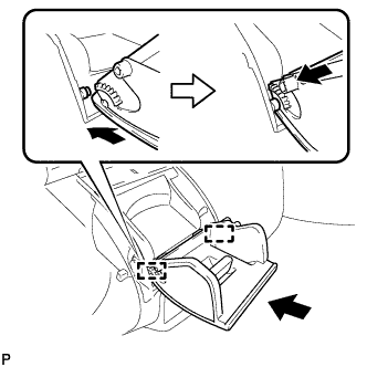 |
Install the 2 hinges of the cup holder one at a time.
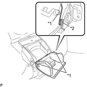 |
Flex both sides of the cup holder and engage the 2 stoppers.
| *1 | Runner Portion |
| *2 | Spring |
Remove protective tape.
Close the instrument panel cup holder.
| 36. CHECK SRS WARNING LIGHT |