DTC P0136 Oxygen Sensor Circuit Malfunction (Bank 1 Sensor 2) |
| DTC No. | DTC Detection Condition | Trouble Area |
| P0136 | Following conditions (a) and (b) met for 6 minutes or more after engine warmed up (2 trip detection logic):
|
|
All of following conditions (a), (b), (c), (d) and (e) met (2 trip detection logic):
|
| Required Sensor/Components (Main) | Heated oxygen sensor (sensor 2) |
| Required Sensor/Components (Related) | Engine coolant temperature sensor, Mass air flow meter, vehicle speed sensor, Throttle with motor body assembly |
| Frequency of operation | Once per driving cycle |
| All of the following conditions A to C are met | - |
| A. Engine | Running |
| B. Time after engine starts | 0 seconds or more |
| C. Cumulative time while heated oxygen sensor is ON | 22 seconds or more |
| All of the following conditions A to E are met | - |
| A. Engine | Running |
| B. Vehicle speed | 3 km/h (1.864 mph) or higher |
| C. Idle | OFF |
| D. Fuel cut | OFF |
| E. Cumulative time while heated oxygen sensor heater is ON | 120 seconds or more |
| All of the following conditions are met | - |
| Frequency of switch time between less than 0.4 V and 0.5 V or more | 0 times |
| Cumulative rear oxygen sensor monitor time | 190 seconds or more |
| All of the following conditions A to E are met | - |
| A. Cumulative heated oxygen sensor monitoring time | 85 seconds or more |
| B. Cumulative time while heated oxygen sensor voltage is below 0.05 V | 60 seconds or more |
| C. Cumulative time while heated oxygen sensor voltage is 0.7 V or higher | Less than 17 seconds |
| D. Cumulative time while heated oxygen sensor voltage is 0.45 V or higher | Less than 17 seconds |
| E. Maximum time while heated oxygen sensor voltage is 0.45 V or higher | Less than 20 seconds |
| Tester Display | Description |
| NORMAL |
|
| ABNORMAL |
|
| INCOMPLETE |
|
| N/A |
|
| Tester Display (Sensor) | Injection Volume | Status | Voltage |
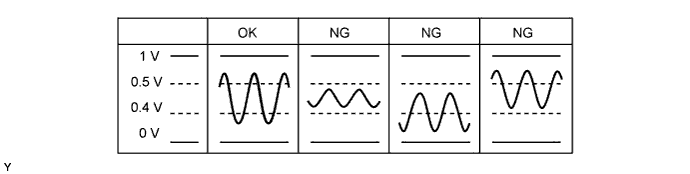
| O2S B1S1 Heated oxygen sensor (sensor 1) | +12% | Rich | Higher than 0.5 V |
| -12% | Lean | Below 0.4 V | |
| O2S B1S2 Heated oxygen sensor (sensor 2) | +12% | Rich | Higher than 0.5 V |
| -12% | Lean | Below 0.4 V |
| Case | Heated Oxygen Sensor (Sensor 1) Output Voltage | Heated Oxygen Sensor (Sensor 2) Output Voltage | Main Suspected Trouble Area |
| 1 |   |  | - |
| 2 |  | |
|
| 3 | | |
|
| 4 | | |
|
| 1.CHECK ANY OTHER DTCS OUTPUT (IN ADDITION TO DTC P0136) |
Connect the intelligent tester to the DLC3.
Turn the ignition switch to ON and turn the tester on.
Enter the following menus: Powertrain / Engine and ECT / DTC.
Read DTCs.
| Result | Proceed to |
| DTC P0136 is output | A |
| DTC P0136 and other DTCs are output | B |
|
| ||||
| A | |
 |
| 2.READ VALUE USING INTELLIGENT TESTER (O2S B1S2) |
Connect the intelligent tester to the DLC3.
Turn the ignition switch to ON and turn the tester on.
Enter the following menus: Powertrain / Engine and ECT / Data List / O2S B1S2.
Allow the engine to run at 2500 rpm for 3 minutes.
Depress the accelerator pedal quickly until the engine rpm reaches 4000 rpm 3 times.
| Result | Proceed to |
| NG | A |
| OK | B |
|
| ||||
| A | |
|
| 3.INSPECT HEATED OXYGEN SENSOR (HEATER RESISTANCE OF HEATED OXYGEN SENSOR (SENSOR 2)) |
Inspect the heated oxygen sensor (sensor 2) (Click here).
|
| ||||
| OK | |
|
| 4.CHECK TERMINAL VOLTAGE (POWER SOURCE OF HEATED OXYGEN SENSOR (SENSOR 2)) |
Disconnect the heated oxygen sensor (sensor 2) connector.
Turn the ignition switch to ON.
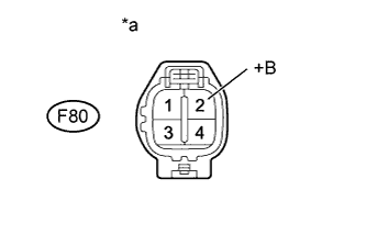 |
Measure the voltage according to the value(s) in the table below.
| Tester Connection | Switch Condition | Specified Condition |
| F80-2 (+B) - Body ground | Ignition switch ON | 11 to 14 V |
| *a | Front view of wire harness connector (to Heated Oxygen Sensor (Sensor 2)) |
|
| ||||
| OK | |
|
| 5.CHECK HARNESS AND CONNECTOR (HEATED OXYGEN SENSOR (SENSOR 2) - ECM) |
Disconnect the heated oxygen sensor (sensor 2) connector.
Disconnect the ECM connector.
Measure the resistance according to the value(s) in the table below.
| Tester Connections | Condition | Specified Condition |
| F80-1 (HT1B) - B84-47 (HT1B) | Always | Below 1 Ω |
| F80-3 (OX1B) - B84-64 (OX1B) | Always | Below 1 Ω |
| F80-4 (E2) - B84-87 (EX1B) | Always | Below 1 Ω |
| F80-1 (HT1B) - B84-47 (HT1B) - Body ground | Always | 10 kΩ or higher |
| F80-3 (OX1B) - B84-64 (OX1B) - Body ground | Always | 10 kΩ or higher |
| F80-4 (E2) - B84-87 (EX1B) - Body ground | Always | 10 kΩ or higher |
|
| ||||
| OK | ||
 | ||
| ||
| 6.CHECK HARNESS AND CONNECTOR (NO. 1 INTEGRATION RELAY - HEATED OXYGEN SENSOR (SENSOR 2)) |
Disconnect the heated oxygen sensor (sensor 2) connector.
Remove the No. 1 integration relay from the engine room relay block.
Measure the resistance according to the value(s) in the table below.
| Tester Connection | Condition | Specified Condition |
| F80-2 (+B) - 1D-11 | Always | Below 1 Ω |
| F80-2 (+B) or 1D-11 - Body ground | Always | 10 kΩ or higher |
|
| ||||
| OK | ||
| ||
| ||
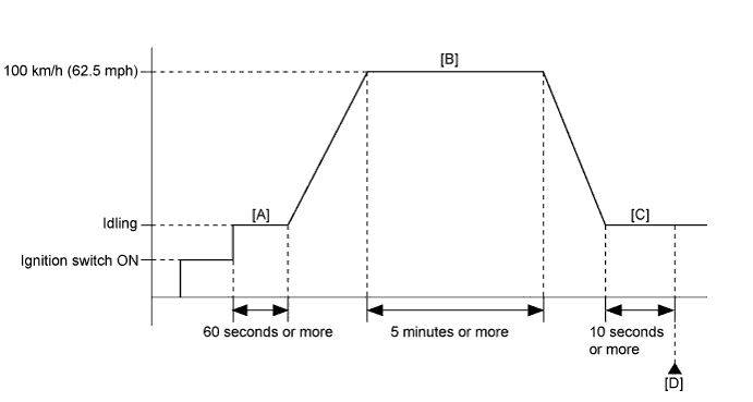
| 7.PERFORM CONFIRMATION DRIVING PATTERN |
Drive the vehicle in accordance with the driving pattern described in Confirmation Driving Pattern.
| NEXT | |
|
| 8.CHECK WHETHER DTC OUTPUT RECURS (DTC P0136) |
Connect the intelligent tester to the DLC3.
Turn the ignition switch to ON and turn the tester on.
Enter the following menus: Powertrain / Engine and ECT / DTC.
Read the DTCs.
| Result | Proceed to |
| DTC P0136 is output | A |
| DTC is not output | B |
|
| ||||
| A | ||
| ||
| ||

