AUTOMATIC TRANSAXLE ASSEMBLY > INSTALLATION |
| 1. INSTALL WIRE HARNESS CLAMP BRACKET |
Install the 3 wire harness clamp brackets with the 3 bolts.
| 2. INSTALL TRANSMISSION OIL FILLER TUBE SUB-ASSEMBLY |
Apply Toyota Genuine ATF WS to a new O-ring, and install it to the transmission oil filler tube sub-assembly.
Install the transmission oil filler tube sub-assembly to the automatic transaxle assembly with the bolt.
Connect the breather hose to the transmission oil filler tube sub-assembly.
| 3. INSTALL TRANSMISSION OIL LEVEL DIPSTICK SUB-ASSEMBLY |
Install the transmission oil level dipstick sub-assembly into the transmission oil filler tube sub-assembly.
| 4. INSTALL NO. 2 OIL COOLER TUBE CLAMP |
Temporarily install the outlet No. 1 oil cooler tube to the oil cooler tube union.
Temporarily install the inlet No. 1 oil cooler tube to the oil cooler tube union.
Install the No. 2 oil cooler tube clamp to the transmission oil filler tube sub-assembly with the bolt.
| 5. CONNECT OUTLET NO. 1 OIL COOLER TUBE |
![]() |
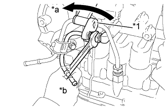
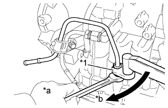
Using a union nut wrench 14 mm, connect the outlet No. 1 oil cooler tube while holding the oil cooler tube union with a wrench.
| *1 | Union Nut Wrench 14 mm |
| *a | Hold |
| *b | Turn |
| 6. CONNECT INLET NO. 1 OIL COOLER TUBE |
![]() |
Using a union nut wrench 14 mm, connect the inlet No. 1 oil cooler tube while holding the oil cooler tube union with a wrench.
| *1 | Union Nut Wrench 14 mm |
| *a | Turn |
| *b | Hold |
| 7. INSTALL NO. 1 TRANSMISSION CONTROL CABLE BRACKET |
Install the No. 1 transmission control cable bracket to the automatic transaxle assembly with the 2 bolts.
| 8. INSTALL SPEEDOMETER DRIVEN HOLE COVER SUB-ASSEMBLY |
Apply Toyota Genuine ATF WS to a new O-ring, and install it to the speedometer driven hole cover.
Install the speedometer driven hole cover sub-assembly to the automatic transaxle assembly.
| 9. INSPECT TORQUE CONVERTER ASSEMBLY |
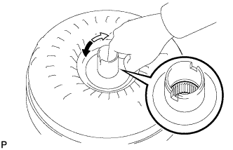
Inspect the one-way clutch.
![]() |
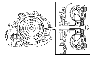
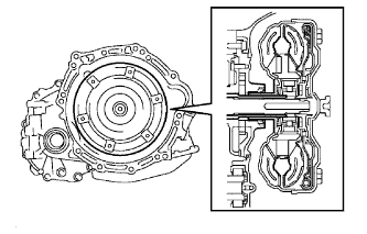
Press on the splines of the stator with a finger and rotate it. Check that it rotates smoothly when turned clockwise and rotates with difficulty when turned counterclockwise.
![]() | Difficult |
![]() | Smooth |
![]() |
Inspect the torque converter assembly.
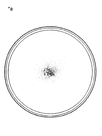
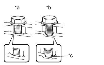
If any of the following problems are present, replace the torque converter assembly.
| *a | Sample showing maximum allowable amount of powder in ATF |
Replace the ATF in the torque converter assembly.
If the ATF is discolored or has a foul odor, stir the ATF in the torque converter assembly before replacing the ATF.
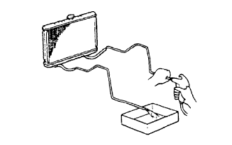
Clean and check the oil cooler and oil pipe line.
![]() |
![]() |
Prevent deformation of the torque converter assembly and damage to the oil pump gear.
| *a | Correct |
| *b | Incorrect |
| *c | Bottom is damaged |
| 10. INSTALL TORQUE CONVERTER ASSEMBLY |
![]() |
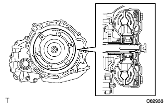
Engage the splines of the input shaft and turbine runner.
![]() |
Engage the splines of the stator shaft and the stator while turning the torque converter assembly.
![]() |
Turn the torque converter assembly to insert the key of the oil pump drive gear into the groove of the torque converter assembly.
Clean the torque converter setting bolt holes.
![]() |
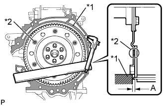
Using a vernier caliper and a straightedge, measure dimension A between the transaxle contact surface of the engine and the torque converter contact surface of the drive plate.
| *1 | Engine Surface |
| *2 | Drive Plate Surface |
![]() |
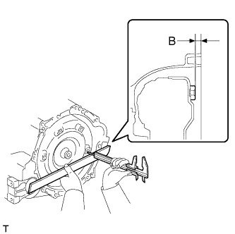
Using a vernier caliper and straightedge, measure dimension B shown in the illustration and check that dimension B is more than dimension A, which was measured in the previous step.
| 11. INSTALL AUTOMATIC TRANSAXLE ASSEMBLY |
![]() |
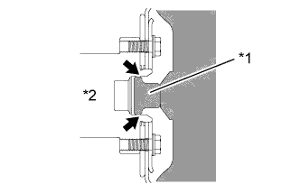
Apply clutch spline grease to the round of the crankshaft contact surface with the torque converter centerpiece.
| *1 | Torque Converter Centerpiece |
| *2 | Crankshaft |
![]() | Clutch spline grease |
![]() |
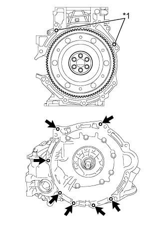
Confirm that 2 knock pins are on the transaxle contact surface of the engine cylinder block before transaxle installation.
| *1 | Knock Pin |
Keeping the engine assembly and the automatic transaxle assembly in a horizontal position, align the knock pins with each hole on the automatic transaxle assembly and tighten the 7 bolts.
| 12. INSTALL ENGINE MOUNTING BRACKET LH |
![]() |
Clean and degrease the bolt and the bolt installation hole.
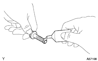
Apply adhesive to 2 or 3 threads on the end of the 4 bolts.
Install the engine mounting bracket LH to the automatic transaxle assembly with the 4 bolts.
Install the engine mounting insulator LH to the engine mounting bracket LH with the bolt and nut.
| 13. INSTALL ENGINE MOVING CONTROL ROD BRACKET |
Install the engine moving control rod bracket to the automatic transaxle assembly with the 3 bolts.
| 14. INSTALL TORQUE CONVERTER SETTING BOLT |
![]() |
Remove any adhesive remaining in the 6 torque converter setting bolts.
Apply adhesive to 2 or 3 threads on the end of the 6 torque converter setting bolts.
Use SST to hold the crankshaft pulley in place.
Install the 6 torque converter setting bolts.
| 15. INSTALL FLYWHEEL HOUSING UNDER COVER |
Install the flywheel housing under cover.
| 16. INSTALL FRONT SUSPENSION CROSSMEMBER SUB-ASSEMBLY |
| 17. INSTALL FRONT DRIVE SHAFT ASSEMBLIES |
| 18. CONNECT OUTLET OIL COOLER HOSE |
Connect the outlet oil cooler hose with the clip.
| 19. CONNECT INLET OIL COOLER HOSE |
Connect the inlet oil cooler hose with the clip.
| 20. INSTALL WIRE HARNESS |
Engage the 7 clamps and install the wire harness.
Connect the transmission revolution sensor connector.
Connect the transmission wire connector.
Connect the park/neutral position switch connector.
Install the No. 3 engine wire to the automatic transaxle assembly with the bolt.
| 21. INSTALL TRANSMISSION CONTROL CABLE ASSEMBLY |
![]() |
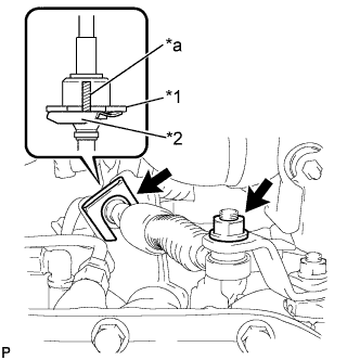
Install the transmission control cable assembly to the control shaft lever with the nut.
| *1 | No. 1 Transmission Control Cable Bracket |
| *2 | Clip |
| *a | Marking |
Install the transmission control cable assembly to the No. 1 transmission control cable bracket with a new clip.
| 22. INSTALL STARTER ASSEMBLY |
| 23. INSTALL AIR CLEANER BRACKET |
Install the air cleaner bracket with the 2 bolts.
Connect the wire harness clamp to the air cleaner bracket.
| 24. INSTALL AIR CLEANER ASSEMBLY |
Install the air cleaner case onto the air cleaner bracket with the 2 bolts.
Engage the clamp and connect the wire harness to the air cleaner case.
Install the air cleaner element onto the air cleaner case.
Install the air cleaner cap sub-assembly with No. 1 air cleaner hose onto the throttle body assembly.
Engage the 2 clamps and connect the air cleaner cap sub-assembly to the air cleaner case subassembly.
Tighten the hose clamp.
Connect the vacuum switching valve assembly connector.
Connect the mass air flow meter connector.
Engage the 2 clamps and connect the wire harness to the air cleaner cap sub-assembly and vacuum switching valve assembly.
Connect the No. 2 fuel vapor feed hose to the intake manifold.
Connect the fuel vapor feed hose assembly to the No. 1 air cleaner hose and vacuum switching valve assembly with the 2 hose clamps.
Engage the clamp and connect the fuel vapor feed hose assembly to the No. 1 air cleaner hose.
| 25. INSTALL BATTERY CARRIER (for LHD) |
Install the battery carrier with the 5 bolts.
Engage the 6 wire harness clamps and install the wire harness.
| 26. INSTALL BATTERY CARRIER (for RHD) |
Install the battery carrier with the 5 bolts.
Engage the 7 wire harness clamps and install the wire harness.
| 27. INSTALL BATTERY TRAY |
| 28. INSTALL BATTERY |
Install the battery onto the vehicle with the battery clamp.
Connect the cable to the battery terminal.
| 29. ADD AUTOMATIC TRANSAXLE FLUID |
| Classification | Capacity (Reference) | |
| Toyota Genuine ATF WS | Dry fill | 6.4 liters (6.8 US qts, 5.6 Imp. qts) |
| Drain and refill | 2.5 liters (2.6 US qts, 2.2 Imp. qts) | |
| 30. INSPECT AUTOMATIC TRANSAXLE FLUID |
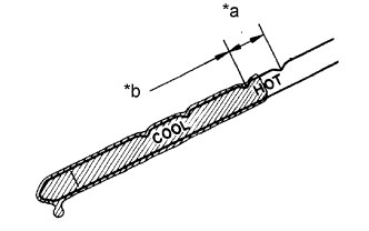
![]() |
| *a | OK if hot |
| *b | Add if hot |
Park the vehicle on a level surface and engage the parking brake.
With the engine idling and the brake pedal depressed, shift the shift lever into all positions from P to L, and then return it to P.
Pull out the oil level dipstick and wipe it clean.
Push it fully back into the pipe.
Pull it out and check that the fluid level is within the HOT range.
If there is any leakage, repair or replace O-rings, seal packing, oil seals, plugs or other parts.
| 31. INSPECT FOR AUTOMATIC TRANSAXLE FLUID LEAK |
| 32. ADJUST SHIFT LEVER POSITION |
| 33. INSPECT SHIFT LEVER POSITION |
Turn the ignition switch to ON and step on the brake pedal.
Confirm that the shift lever moves smoothly through all of the shift positions and the position indicator shows the correct shift lever position.
Start the engine and confirm that the vehicle moves forward when the shift lever is moved from N to D.
| 34. RESET MEMORY (AT initialization) |
Perform Reset Memory (AT initialization) when replacing the automatic transaxle assembly (Click here).