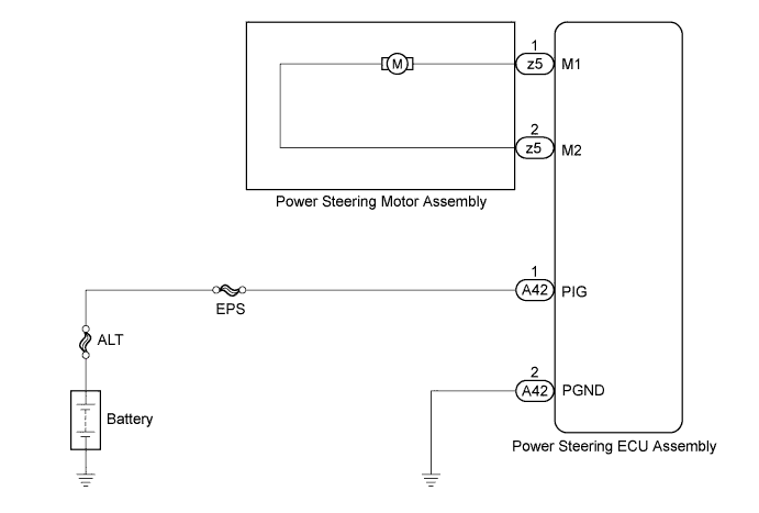
DTC C1524 Motor Circuit Malfunction |
DTC C1555 Motor Relay Welding Failure |
| DTC No. | DTC Detection Condition | Trouble Area |
| C1524 | Short (or open) in motor circuit or abnormal voltage or current in motor circuit. |
|
| C1555 | Motor relay circuit malfunction. |
|
| 1.INSPECT POWER STEERING ECU ASSEMBLY |
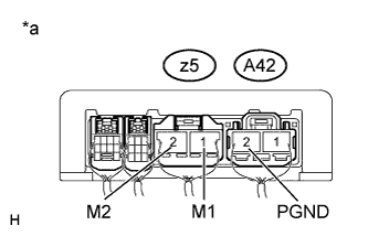 |
Start the engine.
Measure the voltage according to the value(s) in the table below.
| Tester Connection | Condition | Specified Condition |
| z5-1 (M1) - A42-2 (PGND) | Engine running Steering wheel turned to right | 11 to 14 V |
| Engine running steering wheel turned to left | 6 to 11 V | |
| z5-2 (M2) - A42-2 (PGND) | Engine running Steering wheel turned to right | 6 to 11 V |
| Engine running steering wheel turned to left | 11 to 14 V |
| *a | Component with harness connected (Power Steering ECU Assembly) |
|
| ||||
| OK | |
 |
| 2.INSPECT POWER STEERING MOTOR ASSEMBLY |
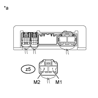 |
Disconnect the power steering ECU assembly connector.
Measure the resistance according to the value(s) in the table below.
| Tester Connection | Condition | Specified Condition |
| z5-1 (M1) - z5-2 (M2) | Always | 0.1 to 1.0 Ω |
| z5-1 (M1) - Body ground | Always | 1 MΩ or higher |
| z5-2 (M2) - Body ground | Always | 1 MΩ or higher |
| *a | Rear view of wire harness connector (to Power Steering ECU Assembly) |
| Result | Proceed to |
| OK | A |
| NG (for LHD) | B |
| NG (for RHD) | C |
|
| ||||
|
| ||||
| A | |
|
| 3.CHECK HARNESS AND CONNECTOR (POWER STEERING ECU ASSEMBLY - BATTERY AND BODY GROUND) |
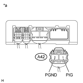 |
Disconnect the power steering ECU assembly connector.
Measure the voltage according to the value(s) in the table below.
| Tester Connection | Condition | Specified Condition |
| A42-1 (PIG) - Body ground | Always | 11 to 14 V |
Measure the resistance according to the value(s) in the table below.
| Tester Connection | Condition | Specified Condition |
| A42-2 (PGND) - Body ground | Always | Below 1 Ω |
| *a | Rear view of wire harness connector (to Power Steering ECU Assembly) |
| Result | Proceed to |
| NG | A |
| OK (for LHD) | B |
| OK (for RHD) | C |
|
| ||||
|
| ||||
| A | ||
 | ||
| ||

