 |
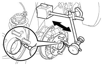
Using a dial indicator, check the backlash near the center of the axle hub.
- Maximum:
- 0.05 mm (0.00197 in.)
REAR SPEED SENSOR > INSTALLATION |
| 1. INSTALL REAR AXLE HUB AND BEARING ASSEMBLY |
Install the axle hub and bearing onto the axle beam with the 4 bolts.
| 2. INSPECT REAR AXLE HUB BEARING BACKLASH |
|
Using a dial indicator, check the backlash near the center of the axle hub.
| 3. INSPECT REAR AXLE HUB RUNOUT |
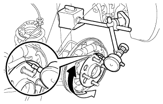 |
Using a dial indicator, check the runout of the surface of the axle hub.
| 4. CONNECT SKID CONTROL SENSOR WIRE |
Connect the skid control sensor wire connector.
| 5. INSTALL REAR BRAKE DRUM SUB-ASSEMBLY |
| 6. ADJUST REAR DRUM BRAKE SHOE CLEARANCE |
Provisionally install the hub nuts.
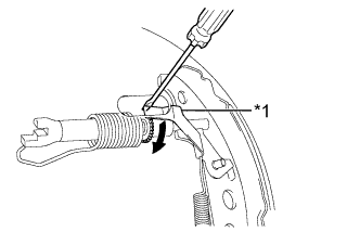 |
Remove the hole plug, and turn the adjuster to expand the shoe until the drum locks.
| *1 | Automatic Adjust Lever |
 | Expand |
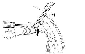 |
Hold the automatic adjust lever away from the adjuster, and contract the brake shoe by turning the adjust bolt using another screwdriver until the drum can rotate smoothly.
| *1 | Automatic Adjust Lever |
| Contract |
Install the hole plug.
| 7. INSTALL REAR WHEEL |
| 8. INSPECT REAR WHEEL ALIGNMENT |
| 9. CHECK ABS SENSOR SIGNAL (w/o VSC) |
| 10. CHECK VSC SENSOR SIGNAL (w/ VSC) |