C107D-BRAKE PEDAL SWITCH 1/2 CORRELATION
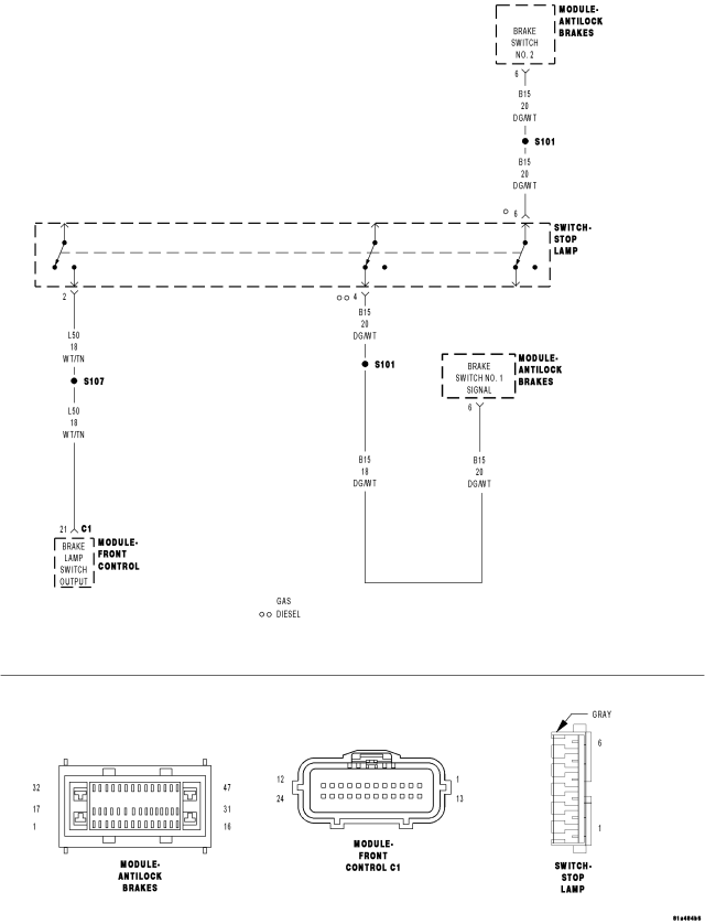
For a complete wiring diagram Refer to Section 8W.
- When Monitored:
When the vehicle is driven.
- Set Condition:
If the Anti-Lock Brakes Module detects an implausible signal from the Stop Lamp Switch.
| Possible Causes |
| WIRING HARNESS, TERMINAL, CONNECTOR DAMAGE |
| BRAKE SWITCH CIRCUIT FOR A OPEN (Z904) GROUND |
| MISADJUSTED PEDAL SWITCH |
| (B15) BRAKE SWITCH NO. 1 SIGNAL CIRCUIT SHORTED TO GROUND |
| (B15) BRAKE SWITCH NO. 1 SIGNAL CIRCUIT OPEN |
| STOP LAMP SWITCH |
| ANTI-LOCK BRAKES MODULE |
Diagnostic Test
1. VERIFY DTC IS ACTIVENOTE: Diagnose and repair all Pressure Sensor and Voltage related DTCs and all Stop Lamp related DTCs and symptoms before diagnosing this DTC.
Turn the ignition on.
With the scan tool, read ABS DTCs.
With the scan tool, read and record Environmental Data (EV Data).
With the scan tool, erase DTCs.
Cycle the ignition switch.
WARNING: Ensure brake capability is available before road testing.
Test drive the vehicle as follows: Drive for more than 6 minutes at a speed greater than 40 km/h (25 mph) and accelerate to a speed greater than 40 km/h (25 mph) and then decelerate to a speed lower than 3 km/h (2 mph) five consecutive times.
Park the vehicle.
With the scan tool, read ABS DTCs.
Does this DTC reset?
Yes
- Go To 2
No
- The condition that caused the symptom is currently not present. Inspect the related wiring for a possible intermittent condition. Look for any chafed, pierced, pinched, or partially broken wires.
- Refer to the ABS-INTERMITTENT CONDITION TEST. (Refer to 5 - BRAKES - DIAGNOSIS AND TESTING)
2. INSPECT RELATED WIRING HARNESS, TERMINALS, & CONNECTORS
Turn the ignition off.
Visually inspect the related wiring harness. Look for any pinched, chafed, pierced, and partially broken wires.
Visually inspect the related wiring harness connectors. Look for broken, bent, pushed out, and corroded terminals.
Were any problems found?
Yes
- Repair as necessary.
- Perform ABS VERIFICATION TEST. (Refer to 5 - BRAKES - STANDARD PROCEDURE).
No
- Go To 3
3. CHECK (B15) BRAKE SWITCH NO. 1 SIGNAL CIRCUIT FUNCTION WHILE DEPRESSING & RELEASING THE BRAKE PEDAL
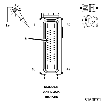
Disconnect the Anti-Lock Brakes Module harness connector.
Turn the ignition on.
Using a 12-volt test light connected to 12 volts, backprobe the (B15) Brake Switch No. 1 Signal circuit in the Anti-Lock Brakes Module harness connector.
Depress and release the brake pedal.
Does the test light illumination toggle from off to on?
Yes
- Go To 7
No
- Go To 4
4. CHECK (B15) BRAKE SWITCH NO. 1 SIGNAL CIRCUIT FOR A SHORT TO GROUND
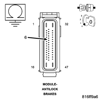
Turn the ignition off.
Disconnect the Stop Lamp Switch harness connector.
Measure the resistance of the (B15) Brake Switch No. 1 Signal circuit between ground and the Anti-Lock Brakes Module harness connector.
Is the resistance below 5.0 ohms?
Yes
- Repair the (B15) Brake Switch No. 1 Signal circuit for a short to ground.
- Perform ABS VERIFICATION TEST. (Refer to 5 - BRAKES - STANDARD PROCEDURE).
No
- Go To 5
5. CHECK (B15) BRAKE SWITCH NO. 1 SIGNAL CIRCUIT FOR AN OPEN
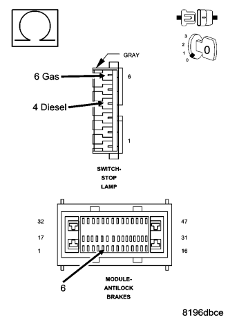
Measure the resistance of the (B15) Brake Switch No. 1 Signal circuit between the Anti-Lock Brakes Module harness connector and the Stop Lamp Switch harness connector.
Is the resistance below 5.0 ohms?
Yes
- Go To 6
No
- Repair the (B15) Brake Switch No. 1 Signal circuit for an open.
- Perform ABS VERIFICATION TEST. (Refer to 5 - BRAKES - STANDARD PROCEDURE).
6. CHECK BRAKE SWITCH CIRCUIT FOR A OPEN (Z904) GROUND
Is the resistance below 5 ohms?
Yes
- Replace the Stop Lamp Switch in accordance with the Service Information.
- Perform ABS VERIFICATION TEST. (Refer to 5 - BRAKES - STANDARD PROCEDURE).
No
- Repair the open in the (Z904) Ground circuit.
7. CHECK BRAKE PEDAL ADJUSTMENT
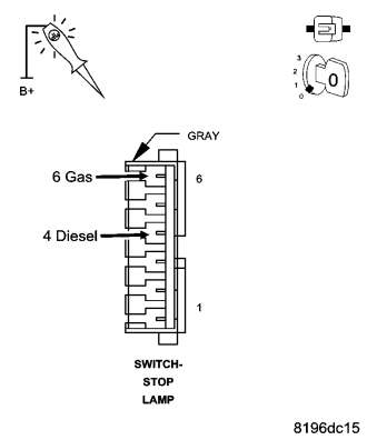
- Reconnect the Stop Lamp Switch harness connector.
Using a 12-volt test light connected to (B15) Brake Switch No. 1 Signal circuit in the Stop Lamp Switch harness connector.
Depress and release the brake pedal.
Does the test light illumination toggle from off to on within 4–5 mm of brake pedal travel?
Yes
- Replace the Anti-Lock Bakes Module in accordance with the Service Information.
- Perform ABS VERIFICATION TEST. (Refer to 5 - BRAKES - STANDARD PROCEDURE).
No
- Replace the Stop Lamp Switch in accordance with the Service Information.
- Perform ABS VERIFICATION TEST. (Refer to 5 - BRAKES - STANDARD PROCEDURE).