P0710-TRANSMISSION TEMPERATURE SENSOR CIRCUIT
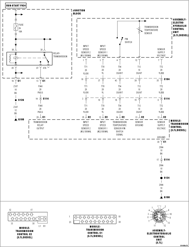
For a complete wiring diagram Refer to Section 8W
Theory of Operation
The Electrohydraulic Control Unit Assembly of the NAG1 transmission contains a temperature sensor to monitor the transmission oil temperature. This sensor is wired in series with the transmission Park/Neutral switch. The Transmission Control Module (TCM) expects to see a valid voltage level from the sensor when the shifter is in Reverse or any forward Drive position. The TCM also expects to see an open circuit condition when the shifter is in the Park or Neutral position. When the controller detects an open circuit when in Reverse or any forward drive position the DTC will set. Note: Due to a open circuit condition in Park or Neutral, the TCM substitutes the Transmission Temperature reading with Engine Temperature when in Park or Neutral
- When Monitored:
Continuously with the ignition on.
- Set Condition:
When the TCM detects an open circuit when in Reverse or any forward drive position the DTC will set.
| Possible Causes |
| SHIFT LEVER ASSEMBLY OUT OF ADJUSTMENT |
| (T54) TEMPERATURE SENSOR-P/N SWITCH SIGNAL CIRCUIT OPEN |
| (T54) TEMPERATURE SENSOR-P/N SWITCH SIGNAL CIRCUIT SHORT TO VOLTAGE |
| (T54) TEMPERATURE SENSOR-P/N SWITCH SIGNAL CIRCUIT SHORT TO OTHER CIRCUITS |
| (T54) TEMPERATURE SENSOR-P/N SWITCH SIGNAL CIRCUIT SHORT TO ANOTHER CIRCUIT(S) |
| SHIFT LEVER ASSEMBLY |
| TRANSMISSION CONTROL MODULE |
Always perform the Pre-Diagnostic Troubleshooting procedure before proceeding. (Refer to 21 - TRANSMISSION/TRANSAXLE/AUTOMATIC - NAG1 - STANDARD PROCEDURE)
Diagnostic Test
1. CHECK IF SPEED SENSOR DTCS ARE PRESENTWith the scan tool, read Transmission DTCs.
Are there any speed sensor DTCs present also?
Yes
- Refer to 21 - TRANSMISSION/TRANSAXLE/AUTOMATIC - NAG1 - DIAGNOSIS & TESTING and perform the appropriate symptom.
No
- Go To 2
2. CHECK IF SHIFT LEVER ASSEMBLY SHIFT CABLE IS OUT OF ADJUSTMENT
Check the Shift Lever Assembly Cable for proper adjustment per the Service Information. (Refer to 21 - TRANSMISSION/TRANSAXLE/AUTOMATIC - NAG1/GEAR SHIFT CABLE - ADJUSTMENTS)
Is the Shift Lever Assembly shift cable properly adjusted?
Yes
- Go To 3
No
- Adjust the Shift Lever Cable per the Service Information.
- Perform NAG1 TRANSMISSION VERIFICATION TEST. (Refer to 21 - TRANSMISSION/TRANSAXLE/AUTOMATIC - NAG1 - STANDARD PROCEDURE)
3. CHECK IF ENGINE STARTS IN PARK OR NEUTRAL
Attempt to start the engine in Park or Neutral.
Does the engine start in either Park or Neutral?
Yes
- Go To 4
No
- Go To 5
4. TRANSMISSION TEMPERATURE SENSOR-P/N SWITCH
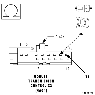
Turn the ignition off to the lock position.
Disconnect the TCM C2 harness connector.
Place the gear selector in Drive.
Measure the resistance of the Transmission Temperature Sensor between the (T54) Temperature Sensor-P/N Switch Signal circuit and the (T13) Sensor Ground circuit in the TCM C2 harness connector.
Is the resistance between 500 to 2500 ohms?
Yes
- Using the schematics as a guide, check the Transmission Control Module (TCM) pins, terminals, and connectors for corrosion, damage, or terminal push out. Pay particular attention to all power and ground circuits. If no problems are found, replace the TCM per the Service Information. (Refer to 8 - ELECTRICAL/ELECTRONIC CONTROL MODULES/TRANSMISSION CONTROL MODULE - REMOVAL)
- Perform NAG1 TRANSMISSION VERIFICATION TEST. (Refer to 21 - TRANSMISSION/TRANSAXLE/AUTOMATIC - NAG1 - STANDARD PROCEDURE)
No
- Using the schematics as a guide, check the Electrohydraulic Control Unit Assembly and Transmission Temperature Sensor-P/N Switch pins and connector terminals for corrosion, damage, or terminal push out. If no problems are found, replace the Transmission Temperature Sensor per the Service Information.
- Perform NAG1 TRANSMISSION VERIFICATION TEST - VER 1. (Refer to 21 - TRANSMISSION/TRANSAXLE/AUTOMATIC - NAG1 - STANDARD PROCEDURE)
5. CHECK THE TRANSMISSION TEMPERATURE SENSOR-P/N SWITCH
Turn the ignition off to the lock position.
Reconnect the TCM C2 harness connector.
Disconnect the Electrohydraulic Control Unit Assembly harness connector.
NOTE: This procedure may set various DTCs to multiple modules connected to the CAN bus. Disregard and erase any DTCs that may set after completion of this procedure.
With the Shift Lever in the Park position, attempt to start the engine.
Does the engine start?
Yes
- Replace the Transmission Temperature per the Service Information.
- Perform NAG1 TRANSMISSION VERIFICATION TEST. (Refer to 21 - TRANSMISSION/TRANSAXLE/AUTOMATIC - NAG1 - STANDARD PROCEDURE)
No
- Go To 6
6. CHECK IF THE (T54) TEMPERATURE SENSOR-P/N SWITCH SIGNAL CIRCUIT IS SHORTED TO GROUND
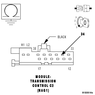
Turn the ignition off to the lock position.
Reconnect the Electrohydraulic Control Unit Assembly harness connector.
Disconnect the TCM C1 and C2 harness connectors.
Measure the resistance between ground and the (T54) Temperature Sensor-P/N Switch Signal circuit.
Is the resistance below 5.0 ohms?
Yes
- Repair the (T54) Temperature Sensor-P/N Switch Signal circuit for a short to ground.
- Perform NAG1 TRANSMISSION VERIFICATION TEST. (Refer to 21 - TRANSMISSION/TRANSAXLE/AUTOMATIC - NAG1 - STANDARD PROCEDURE)
No
- Go To 7
7. CHECK IF (T54) TEMPERATURE SENSOR-P/N SWITCH SIGNAL CIRCUIT IS SHORTED TO ANOTHER CIRCUIT(S)
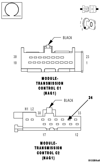
Measure the resistance between the (T54) Temperature Sensor-P/N Switch Signal circuit and all other circuits in the TCM C1 and C2 harness connectors.
Is the resistance below 5.0 ohms between the (T54) Temperature Sensor-P/N Switch Signal circuit and any other circuit(s)?
Yes
- Repair the (T54) Temperature Sensor-P/N Switch Signal circuit for a short to another circuit(s).
- Perform NAG1 TRANSMISSION VERIFICATION TEST. (Refer to 21 - TRANSMISSION/TRANSAXLE/AUTOMATIC - NAG1 - STANDARD PROCEDURE)
No
- Using the schematics as a guide, check the Transmission Control Module (TCM) pins, terminals, and connectors for corrosion, damage, or terminal push out. Pay particular attention to all power and ground circuits. If no problems are found, replace the TCM per the Service Information. Refer to 8 - ELECTRICAL/ELECTRONIC CONTROL MODULES/TRANSMISSION CONTROL MODULE for the appropriate service procedure.
- Perform NAG1 TRANSMISSION VERIFICATION TEST. (Refer to 21 - TRANSMISSION/TRANSAXLE/AUTOMATIC - NAG1 - STANDARD PROCEDURE)