AUTOMATIC TRANSMISSION - NAG1 - SERVICE INFORMATION
- DESCRIPTION
- OPERATION
- STANDARD PROCEDURE - ALUMINUM THREAD REPAIR
- REMOVAL
- DISASSEMBLY
- ASSEMBLY
- INSTALLATION
- SCHEMATICS AND DIAGRAMS
- SPECIFICATIONS
- SPECIAL TOOLS - AUTOMATIC TRANSMISSION - NAG1
DESCRIPTION
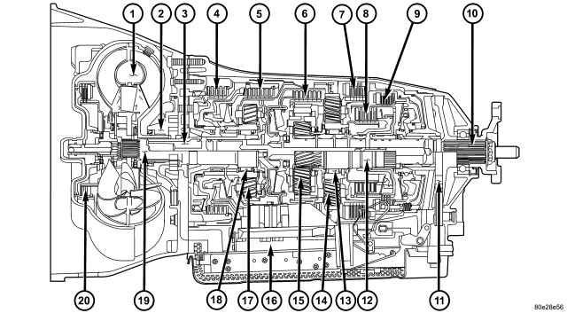
| NAG1 Automatic Transmission |
| 1 - TORQUE CONVERTER |
11 - PARKING LOCK GEAR |
| 2 - OIL PUMP |
12 - INTERMEDIATE
SHAFT |
| 3 - DRIVESHAFT |
13 - FREEWHEEL F2 |
| 4 - MULTI-DISC HOLDING CLUTCH B1 |
14 - REAR PLANETARY GEAR SET |
| 5 - DRIVING CLUTCH
K1 |
15 - CENTER PLANETARY GEAR SET |
| 6 - DRIVING CLUTCH K2 |
16 - ELECTROHYDRAULIC CONTROL UNIT |
| 7 - MULTI-DISC HOLDING CLUTCH B3 |
17 - FRONT PLANETARY GEAR SET |
| 8 - DRIVING CLUTCH K3 |
18 - FREEWHEEL F1 |
| 9 - MULTI-DISC HOLDING CLUTCH B2 |
19 - STATOR SHAFT |
| 10 - OUTPUT SHAFT |
20 - TORQUE CONVERTER LOCK-UP CLUTCH |
The NAG1 automatic transmission is an electronically controlled 5-speed transmission with a lock-up clutch in the torque converter. The ratios for the gear stages are obtained by 3 planetary gear sets. Fifth gear is designed as an overdrive with a high-speed ratio.
NAG1 identifies a family of transmissions and means “N”ew “A”utomatic “G”earbox, generation 1. Various marketing names are associated with the NAG1 family of transmissions, depending on the transmisson variation being used in a specific vehicle. Some examples of the marketing names are: W5A300, W5A380, and W5A580. The marketing name can be interpreted as follows:
- W = A transmission using a hydraulic torque converter.
- 5 = 5 forward gears.
- A = Automatic Transmission.
- 580 = Maximum input torque capacity in Newton meters.
The gears are actuated electronically/hydraulically. The gears are shifted by means of an appropriate combination of three multi-disc holding clutches, three multi-disc driving clutches, and two freewheeling clutches.
Electronic transmission control enables precise adaptation of pressures to the respective operating conditions and to the engine output during the shift phase which results in a significant improvement in shift quality.
Furthermore, it offers the advantage of a flexible adaptation to various vehicle and engines.
Basically, the automatic transmission with electronic control offers the following advantages:
- Reduces fuel consumption.
- Improved shift comfort.
- More favourable step-up through the five gears.
- Increased service life and reliability.
- Lower maintenance costs.
TRANSMISSION IDENTIFICATION
The transmission can be generically identified visually by the presence of a round 13-way connector located near the front corner of the transmission oil pan, on the right side. Specific transmission information can be found stamped into a pad on the left side of the transmission, above the oil pan rail.
TRANSMISSION GEAR RATIOS
The gear ratios for the NAG1 automatic transmission are as follows:
TRANSMISSION HOUSING
The converter housing and transmission are made from a light alloy. These are bolted together and centered via the outer multi-disc carrier of multi-disc holding clutch, B1. A coated intermediate plate provides the sealing. The oil pump and the outer multi-disc carrier of the multi-disc holding clutch, B1, are bolted to the converter housing. The stator shaft is pressed into it and prevented from rotating by splines. The electrohydraulic unit is bolted to the transmission housing from underneath. A sheet metal steel oil pan forms the closure.
MECHANICAL SECTION
The mechanical section consists of a input shaft, output shaft, a sun gear shaft, and three planetary gear sets which are coupled to each other. The planetary gear sets each have four planetary pinion gears. The oil pressure for the torque converter lock-up clutch and clutch K2 is supplied through bores in the input shaft. The oil pressure to clutch K3 is transmitted through the output shaft. The lubricating oil is distributed through additional bores in both shafts. All the bearing points of the gear sets, as well as the freewheeling clutches and actuators, are supplied with lubricating oil. The parking lock gear is connected to the output shaft via splines.
Freewheeling clutches F1 and F2 are used to optimize the shifts. The front freewheel, F1, is supported on the extension of the stator shaft on the transmission side and, in the locking direction, connects the sun gear of the front planetary gear set to the transmission housing. In the locking direction, the rear freewheeling clutch, F2, connects the sun gear of the center planetary gear set to the sun gear of the rear planetary gear set.
ELECTROHYDRAULIC CONTROL UNIT
The electrohydraulic control unit comprises the shift plate made from light alloy for the hydraulic control and an electrical control unit. The electrical control unit comprises of a supporting body made of plastic, into which the electrical components are assembled. The supporting body is mounted on the shift plate and screwed to it.
Strip conductors inserted into the supporting body make the connection between the electrical components and a plug connector. The connection to the wiring harness on the vehicle and the transmission control module (TCM) is produced via this 13-pin plug connector with a bayonet lock.
SHIFT GROUPS
The hydraulic control components (including actuators) which are responsible for the pressure distribution before, during, and after a gear change are described as a shift group. Each shift group contains a command valve, a holding pressure shift valve, a shift pressure shift valve, overlap regulating valve, and a solenoid.
The hydraulic system contains three shift groups: 1-2/4-5, 2-3, and 3-4. Each shift group can also be described as being in one of two possible states. The active shift group is described as being in the shift phase when it is actively engaging/disengaging a clutch combination. The 1-2/4-5 shift group control the B1 and K1 clutches. The 2-3 shift group controls the K2 and K3 clutches. The 3-4 shift group controls the K3 and B2 clutches.
OPERATION
The transmission control is divided into the electronic and hydraulic transmission control functions. While the electronic transmission control is responsible for gear selection and for matching the pressures to the torque to be transmitted, the transmission's power supply control occurs via hydraulic elements in the electrohydraulic control module. The oil supply to the hydraulic elements, such as the hydrodynamic torque converter, the shift elements and the hydraulic transmission control, is provided by way of an oil pump connected with the torque converter.
The Transmission Control Module (TCM) allows for the precise adaptation of pressures to the corresponding operating conditions and to the engine output during the gearshift phase, resulting in a noticeable improvement in shift quality. The engine speed limit can be reached in the individual gears at full throttle and kickdown. The shift range can be changed in the forward gears while driving, but the TCM employs a downshift safeguard to prevent over-revving the engine. The system offers the additional advantage of flexible adaptation to different vehicle and engine variants.
EMERGENCY RUNNING FUNCTION
In order to ensure a safe driving state and to prevent damage to the automatic transmission, the TCM control module switches to limp-home mode in the event of critical faults. A DTC assigned to the fault is stored in memory. All solenoid and regulating valves are thus de-energized.
The net effect is:
- The last engaged gear remains engaged.
- The modulating pressure and shift pressures rise to the maximum levels.
- The torque converter lockup clutch is deactivated.
In order to preserve the operability of the vehicle to some extent, the hydraulic control can be used to engage 2nd gear or reverse using the following procedure:
- Stop the vehicle.
- Move selector lever to "P".
- Switch off engine.
- Wait at least 10 seconds.
- Start engine.
- Move selector lever to D: 2nd gear.
- Move selector lever to R: Reverse gear.
The limp-home function remains active until the DTC is rectified or the stored DTC is erased with the DRB® tool. Sporadic faults can be reset via ignition OFF/ON.
CLUTCH APPLICATION
Refer to CLUTCH APPLICATION for which shift elements are applied in each gear position.
| GEAR |
RATIO |
B1 |
B2 |
B3 |
K1 |
K2 |
K3 |
F1 |
F2 |
| 1 |
3.59 |
X* |
X |
X* |
X |
X |
|||
| 2 |
2.19 |
X |
X |
X* |
X |
||||
| 3 |
1.41 |
X |
X |
X |
|||||
| 4 |
1.00 |
X |
X |
X |
|||||
| 5 |
0.83 |
X |
X |
X |
X* |
||||
| N |
X |
X |
|||||||
| R |
3.16 |
X* |
X |
X |
X |
||||
| R (4WD Low or Limp-in) |
1.93 |
X |
X |
X |
|||||
| * = The shift components required during coast. |
|||||||||
FIRST GEAR POWERFLOW
| 1 - TORQUE CONVERTER LOCK-UP CLUTCH |
14 - CENTER PLANETARY CARRIER |
| 2 - TORQUE CONVERTER TURBINE |
15 - REAR PLANETARY CARRIER |
| 3 - TORQUE CONVERTER IMPELLER |
16 - TORQUE CONVERTER STATOR |
| 4 - HOLDING CLUTCH B1 |
17 - FRONT PLANETARY PINION GEARS |
| 5 - HOLDING CLUTCH B3 |
18 - CENTER PLANETARY PINION GEARS |
| 6 - HOLDING CLUTCH B2 |
19 - REAR PLANETARY PINION GEARS |
| 7 - DRIVING CLUTCH K1 |
20 - FREEWHEELING CLUTCH F1 |
| 8 - FRONT PLANETARY ANNULUS GEAR |
21 - FRONT PLANETARY SUN GEAR |
| 9 - DRIVING CLUTCH K2 |
22 - CENTER PLANETARY SUN GEAR |
| 10 - CENTER PLANETARY ANNULUS GEAR |
23 - REAR PLANETARY SUN GEAR |
| 11 - REAR PLANETARY ANNULUS GEAR |
24 - FREEWHEELING CLUTCH F2 |
| 12 - DRIVING CLUTCH K3 |
25 - INPUT SHAFT |
| 13 - FRONT PLANETARY CARRIER |
26 - OUTPUT SHAFT |
| A - ENGINE SPEED |
D - SECOND GEAR RATIO |
| B - TRANSMISSION INPUT SPEED |
E - THIRD GEAR RATIO |
| C - FIRST GEAR RATIO |
F - FIXED PARTS |
| 1 - TORQUE CONVERTER LOCK-UP CLUTCH |
14 - CENTER PLANETARY CARRIER |
| 2 - TORQUE CONVERTER TURBINE |
15 - REAR PLANETARY CARRIER |
| 3 - TORQUE CONVERTER IMPELLER |
16 - TORQUE CONVERTER STATOR |
| 4 - HOLDING CLUTCH B1 |
17 - FRONT PLANETARY PINION GEARS |
| 5 - HOLDING CLUTCH B3 |
18 - CENTER PLANETARY PINION GEARS |
| 6 - HOLDING CLUTCH B2 |
19 - REAR PLANETARY PINION GEARS |
| 7 - DRIVING CLUTCH K1 |
20 - FREEWHEELING CLUTCH F1 |
| 8 - FRONT PLANETARY ANNULUS GEAR |
21 - FRONT PLANETARY SUN GEAR |
| 9 - DRIVING CLUTCH K2 |
22 - CENTER PLANETARY SUN GEAR |
| 10 - CENTER PLANETARY ANNULUS GEAR |
23 - REAR PLANETARY SUN GEAR |
| 11 - REAR PLANETARY ANNULUS GEAR |
24 - FREEWHEELING CLUTCH F2 |
| 12 - DRIVING CLUTCH K3 |
25 - INPUT SHAFT |
| 13 - FRONT PLANETARY CARRIER |
26 - OUTPUT SHAFT |
| A - ENGINE SPEED |
D - SECOND GEAR RATIO |
| B - TRANSMISSION INPUT SPEED |
E - THIRD GEAR RATIO |
| C - FIRST GEAR RATIO |
F - FIXED PARTS |
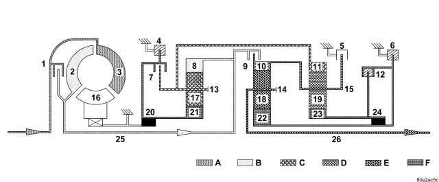
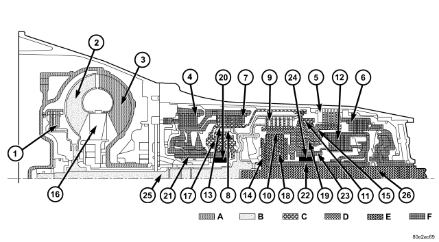
Torque from the torque converter is increased via the input shaft (25) and all three planetary gearsets and transferred to the output shaft (26).
Front Planetary Gear Set
The annulus gear (8) is driven by the input shaft (25). The sun gear (21) is held against the housing by the locked freewheel F1 (20) during acceleration and via the engaged multiple-disc holding clutch B1 (4) during deceleration. The planetary pinion gears (17) turn on the fixed sun gear (21) and increase the torque from the annulus gear (8) to the planetary carrier (13). The planetary carrier (13) moves at a reduced speed in the running direction of the engine.
Rear Planetary Gear Set
The annulus gear (11) turns at a reduced speed due to the mechanical connection to the front planetary carrier (13). The sun gear (23) is held against the housing by the engaged multiple-disc holding clutch B2 (6), by the locked freewheel F2 (24) during acceleration and by the engaged multiple-disc clutch K3 (12) during deceleration. The planetary gears (19) turn on the fixed sun gear (23) and increase the torque from the annulus gear (11) to the planetary carrier (15). The planetary carrier (15) moves at a reduced speed in the running direction of the engine.
Center Planetary Gear Set
The annulus gear (10) is driven at the same speed as the rear planetary carrier (15) as a result of a mechanical connection. The sun gear (22) is held against the housing by the multiple-disc holding clutch B2 (6). The planetary pinion gears (18) turn on the fixed sun gear (22) and increase the torque from the annulus gear (10) to the planetary carrier (14). The output shaft (26) connected to the planetary carrier (14) turns at a reduced speed in the running direction of the engine.
SECOND GEAR POWERFLOW
| 1 - TORQUE CONVERTER LOCK-UP CLUTCH |
14 - CENTER PLANETARY CARRIER |
| 2 - TORQUE CONVERTER TURBINE |
15 - REAR PLANETARY CARRIER |
| 3 - TORQUE CONVERTER IMPELLER |
16 - TORQUE CONVERTER STATOR |
| 4 - HOLDING CLUTCH B1 |
17 - FRONT PLANETARY PINION GEARS |
| 5 - HOLDING CLUTCH B3 |
18 - CENTER PLANETARY PINION GEARS |
| 6 - HOLDING CLUTCH B2 |
19 - REAR PLANETARY PINION GEARS |
| 7 - DRIVING CLUTCH K1 |
20 - FREEWHEELING CLUTCH F1 |
| 8 - FRONT PLANETARY ANNULUS GEAR |
21 - FRONT PLANETARY SUN GEAR |
| 9 - DRIVING CLUTCH K2 |
22 - CENTER PLANETARY SUN GEAR |
| 10 - CENTER PLANETARY ANNULUS GEAR |
23 - REAR PLANETARY SUN GEAR |
| 11 - REAR PLANETARY ANNULUS GEAR |
24 - FREEWHEELING CLUTCH F2 |
| 12 - DRIVING CLUTCH K3 |
25 - INPUT SHAFT |
| 13 - FRONT PLANETARY CARRIER |
26 - OUTPUT SHAFT |
| A - ENGINE SPEED |
D - SECOND GEAR RATIO |
| B - TRANSMISSION INPUT SPEED |
E - FIXED PARTS |
| C - FIRST GEAR RATIO |
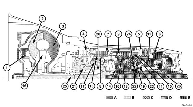
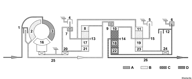
| 1 - TORQUE CONVERTER LOCK-UP CLUTCH |
14 - CENTER PLANETARY CARRIER |
| 2 - TORQUE CONVERTER TURBINE |
15 - REAR PLANETARY CARRIER |
| 3 - TORQUE CONVERTER IMPELLER |
16 - TORQUE CONVERTER STATOR |
| 4 - HOLDING CLUTCH B1 |
17 - FRONT PLANETARY PINION GEARS |
| 5 - HOLDING CLUTCH B3 |
18 - CENTER PLANETARY PINION GEARS |
| 6 - HOLDING CLUTCH B2 |
19 - REAR PLANETARY PINION GEARS |
| 7 - DRIVING CLUTCH K1 |
20 - FREEWHEELING CLUTCH F1 |
| 8 - FRONT PLANETARY ANNULUS GEAR |
21 - FRONT PLANETARY SUN GEAR |
| 9 - DRIVING CLUTCH K2 |
22 - CENTER PLANETARY SUN GEAR |
| 10 - CENTER PLANETARY ANNULUS GEAR |
23 - REAR PLANETARY SUN GEAR |
| 11 - REAR PLANETARY ANNULUS GEAR |
24 - FREEWHEELING CLUTCH F2 |
| 12 - DRIVING CLUTCH K3 |
25 - INPUT SHAFT |
| 13 - FRONT PLANETARY CARRIER |
26 - OUTPUT SHAFT |
| A - ENGINE SPEED |
D - SECOND GEAR RATIO |
| B - TRANSMISSION INPUT SPEED |
E - FIXED PARTS |
| C - FIRST GEAR RATIO |
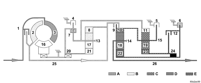
Torque from the torque converter is increased via the input shaft (25) and the center and rear planetary gearset and transferred to the output shaft (26).
Front Planetary Gear Set
The planetary carrier (13) and sun gear (21) are connected via the engaged multiple-disc clutch K1 (7). The planetary gearset is therefore blocked and turns as a closed unit at the input speed due to the mechanical connection of the annulus gear (8) and input shaft.
Rear Planetary Gear Set
The annulus gear (11) turns at the input speed as a result of the mechanical connection to the front planetary carrier (13). The sun gear (23) is held against the housing by the engaged multiple-disc holding clutch B2 (6), by the locked freewheel F2 (24) during acceleration and by the engaged multiple-disc clutch K3 (12) during deceleration. The planetary pinion gears (19) turn on the fixed sun gear (23) and increase the torque from the annulus gear (11) to the planetary carrier (15). The planetary carrier (15) moves at a reduced speed in the running direction of the engine.
Center Planetary Gear Set
The annulus gear (10) is driven at the same speed as the rear planetary carrier (15) as a result of a mechanical connection. The sun gear (22) is held against the housing by the multiple-disc holding clutch B2 (6). The planetary pinion gears (18) turn on the fixed sun gear (22) and increase the torque from the annulus gear (10) to the planetary carrier (14). The output shaft (26) connected to the planetary carrier (14) turns at a reduced speed in the running direction of the engine.
THIRD GEAR POWERFLOW
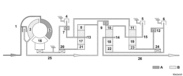
| 1 - TORQUE CONVERTER LOCK-UP CLUTCH |
14 - CENTER PLANETARY CARRIER |
| 2 - TORQUE CONVERTER TURBINE |
15 - REAR PLANETARY CARRIER |
| 3 - TORQUE CONVERTER IMPELLER |
16 - TORQUE CONVERTER STATOR |
| 4 - HOLDING CLUTCH B1 |
17 - FRONT PLANETARY PINION GEARS |
| 5 - HOLDING CLUTCH B3 |
18 - CENTER PLANETARY PINION GEARS |
| 6 - HOLDING CLUTCH B2 |
19 - REAR PLANETARY PINION GEARS |
| 7 - DRIVING CLUTCH K1 |
20 - FREEWHEELING CLUTCH F1 |
| 8 - FRONT PLANETARY ANNULUS GEAR |
21 - FRONT PLANETARY SUN GEAR |
| 9 - DRIVING CLUTCH K2 |
22 - CENTER PLANETARY SUN GEAR |
| 10 - CENTER PLANETARY ANNULUS GEAR |
23 - REAR PLANETARY SUN GEAR |
| 11 - REAR PLANETARY ANNULUS GEAR |
24 - FREEWHEELING CLUTCH F2 |
| 12 - DRIVING CLUTCH K3 |
25 - INPUT SHAFT |
| 13 - FRONT PLANETARY CARRIER |
26 - OUTPUT SHAFT |
| A - ENGINE SPEED |
C - FIRST GEAR RATIO |
| B - TRANSMISSION INPUT SPEED |
D - FIXED PARTS |
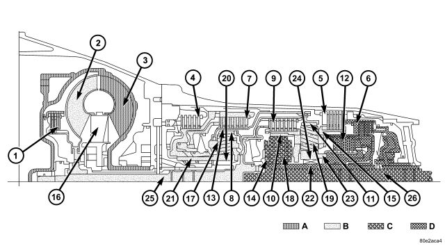
| 1 - TORQUE CONVERTER LOCK-UP CLUTCH |
14 - CENTER PLANETARY CARRIER |
| 2 - TORQUE CONVERTER TURBINE |
15 - REAR PLANETARY CARRIER |
| 3 - TORQUE CONVERTER IMPELLER |
16 - TORQUE CONVERTER STATOR |
| 4 - HOLDING CLUTCH B1 |
17 - FRONT PLANETARY PINION GEARS |
| 5 - HOLDING CLUTCH B3 |
18 - CENTER PLANETARY PINION GEARS |
| 6 - HOLDING CLUTCH B2 |
19 - REAR PLANETARY PINION GEARS |
| 7 - DRIVING CLUTCH K1 |
20 - FREEWHEELING CLUTCH F1 |
| 8 - FRONT PLANETARY ANNULUS GEAR |
21 - FRONT PLANETARY SUN GEAR |
| 9 - DRIVING CLUTCH K2 |
22 - CENTER PLANETARY SUN GEAR |
| 10 - CENTER PLANETARY ANNULUS GEAR |
23 - REAR PLANETARY SUN GEAR |
| 11 - REAR PLANETARY ANNULUS GEAR |
24 - FREEWHEELING CLUTCH F2 |
| 12 - DRIVING CLUTCH K3 |
25 - INPUT SHAFT |
| 13 - FRONT PLANETARY CARRIER |
26 - OUTPUT SHAFT |
| A - ENGINE SPEED |
C - FIRST GEAR RATIO |
| B - TRANSMISSION INPUT SPEED |
D - FIXED PARTS |
Torque from the torque converter is increased via the input shaft (25) and the center planetary gearset and transferred to the output shaft (26).
Front Planetary Gear Set
The planetary carrier (13) and sun gear (21) are connected via the engaged multiple-disc clutch K1 (7). The planetary gearset is therefore locked and turns as a closed unit at the input speed due to the mechanical connection of the annulus gear (8) and input shaft (25).
Rear Planetary Gear Set
The multiple-disc clutch K2 (9) is engaged and transfers the input speed of the input shaft (25) to the planetary carrier (15) via the annulus gear (10). The annulus gear (11) turns in the same way as the planetary carrier (15) due to the mechanical connection with the locked front planetary gearset. This planetary gearset is therefore locked and turns as a closed unit.
Center Planetary Gear Set
The annulus gear (10) turns at the input speed as a result of the engaged multiple-disc clutch K2 (9). The sun gear (22) is held against the housing by the multiple-disc holding clutch B2 (6). The planetary pinion gears (18) turn on the fixed sun gear (22) and increase the torque from the annulus gear (10) to the planetary carrier (14). The output shaft (26) connected to the planetary carrier (14) turns at a reduced speed in the running direction of the engine.
FOURTH GEAR POWERFLOW
| 1 - TORQUE CONVERTER LOCK-UP CLUTCH |
14 - CENTER PLANETARY CARRIER |
| 2 - TORQUE CONVERTER TURBINE |
15 - REAR PLANETARY CARRIER |
| 3 - TORQUE CONVERTER IMPELLER |
16 - TORQUE CONVERTER STATOR |
| 4 - HOLDING CLUTCH B1 |
17 - FRONT PLANETARY PINION GEARS |
| 5 - HOLDING CLUTCH B3 |
18 - CENTER PLANETARY PINION GEARS |
| 6 - HOLDING CLUTCH B2 |
19 - REAR PLANETARY PINION GEARS |
| 7 - DRIVING CLUTCH K1 |
20 - FREEWHEELING CLUTCH F1 |
| 8 - FRONT PLANETARY ANNULUS GEAR |
21 - FRONT PLANETARY SUN GEAR |
| 9 - DRIVING CLUTCH K2 |
22 - CENTER PLANETARY SUN GEAR |
| 10 - CENTER PLANETARY ANNULUS GEAR |
23 - REAR PLANETARY SUN GEAR |
| 11 - REAR PLANETARY ANNULUS GEAR |
24 - FREEWHEELING CLUTCH F2 |
| 12 - DRIVING CLUTCH K3 |
25 - INPUT SHAFT |
| 13 - FRONT PLANETARY CARRIER |
26 - OUTPUT SHAFT |
| A - ENGINE SPEED |
B - TRANSMISSION INPUT SPEED |
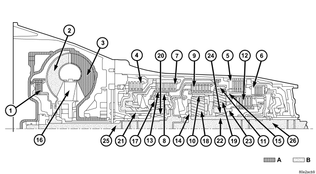
| 1 - TORQUE CONVERTER LOCK-UP CLUTCH |
14 - CENTER PLANETARY CARRIER |
| 2 - TORQUE CONVERTER TURBINE |
15 - REAR PLANETARY CARRIER |
| 3 - TORQUE CONVERTER IMPELLER |
16 - TORQUE CONVERTER STATOR |
| 4 - HOLDING CLUTCH B1 |
17 - FRONT PLANETARY PINION GEARS |
| 5 - HOLDING CLUTCH B3 |
18 - CENTER PLANETARY PINION GEARS |
| 6 - HOLDING CLUTCH B2 |
19 - REAR PLANETARY PINION GEARS |
| 7 - DRIVING CLUTCH K1 |
20 - FREEWHEELING CLUTCH F1 |
| 8 - FRONT PLANETARY ANNULUS GEAR |
21 - FRONT PLANETARY SUN GEAR |
| 9 - DRIVING CLUTCH K2 |
22 - CENTER PLANETARY SUN GEAR |
| 10 - CENTER PLANETARY ANNULUS GEAR |
23 - REAR PLANETARY SUN GEAR |
| 11 - REAR PLANETARY ANNULUS GEAR |
24 - FREEWHEELING CLUTCH F2 |
| 12 - DRIVING CLUTCH K3 |
25 - INPUT SHAFT |
| 13 - FRONT PLANETARY CARRIER |
26 - OUTPUT SHAFT |
| A - ENGINE SPEED |
B - TRANSMISSION INPUT SPEED |
Speed and torque are not converted by the direct gear ratio of the 4th gear. Power is transferred from the input shaft (25) to the output shaft (26) via three locked planetary gearsets.
Front Planetary Gear Set
The planetary carrier (13) and sun gear (21) are connected via the engaged multiple-disc clutch K1 (7). The planetary gearset is therefore locked and turns as a closed unit at the input speed due to the mechanical connection of the annulus gear (8) and the input shaft (25).
Rear Planetary Gear Set
The multiple-disc clutch K2 (9) is engaged and transfers the input speed of the input shaft (25) to the planetary carrier (15) via the annulus gear (10). The annulus gear (11) turns in the same way as the planetary carrier (15) due to the mechanical connection with the locked front planetary gearset. The planetary gearset is therefore locked and turns as a closed unit.
Center Planetary Gear Set
The annulus gear (10) turns at the input speed as a result of the engaged multiple-disc clutch K2 (9). The multiple-disc clutch K3 (12) connects the sun gears (22) and (23) of the rear and center planetary gearset. The planetary gearset is locked by the same speeds of the annulus gear (10) and the sun gear (22) and it turns as a closed unit.
FIFTH GEAR POWERFLOW
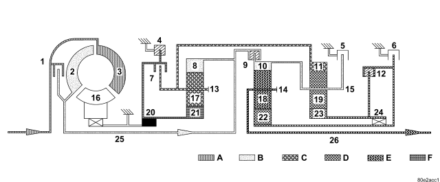
| 1 - TORQUE CONVERTER LOCK-UP CLUTCH |
14 - CENTER PLANETARY CARRIER |
| 2 - TORQUE CONVERTER TURBINE |
15 - REAR PLANETARY CARRIER |
| 3 - TORQUE CONVERTER IMPELLER |
16 - TORQUE CONVERTER STATOR |
| 4 - HOLDING CLUTCH B1 |
17 - FRONT PLANETARY PINION GEARS |
| 5 - HOLDING CLUTCH B3 |
18 - CENTER PLANETARY PINION GEARS |
| 6 - HOLDING CLUTCH B2 |
19 - REAR PLANETARY PINION GEARS |
| 7 - DRIVING CLUTCH K1 |
20 - FREEWHEELING CLUTCH F1 |
| 8 - FRONT PLANETARY ANNULUS GEAR |
21 - FRONT PLANETARY SUN GEAR |
| 9 - DRIVING CLUTCH K2 |
22 - CENTER PLANETARY SUN GEAR |
| 10 - CENTER PLANETARY ANNULUS GEAR |
23 - REAR PLANETARY SUN GEAR |
| 11 - REAR PLANETARY ANNULUS GEAR |
24 - FREEWHEELING CLUTCH F2 |
| 12 - DRIVING CLUTCH K3 |
25 - INPUT SHAFT |
| 13 - FRONT PLANETARY CARRIER |
26 - OUTPUT SHAFT |
| A - ENGINE SPEED |
D - SECOND GEAR RATIO |
| B - TRANSMISSION INPUT SPEED |
E - THIRD GEAR RATIO |
| C - FIRST GEAR RATIO |
F - FIXED PARTS |
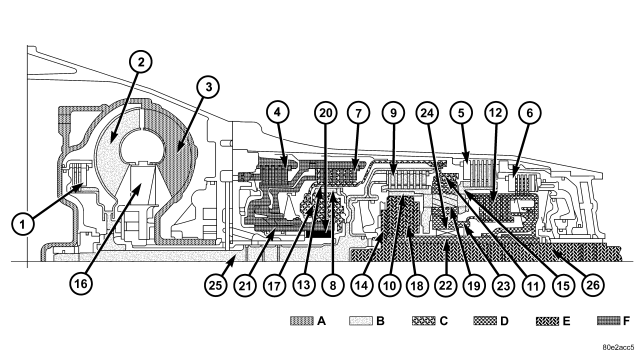
| 1 - TORQUE CONVERTER LOCK-UP CLUTCH |
14 - CENTER PLANETARY CARRIER |
| 2 - TORQUE CONVERTER TURBINE |
15 - REAR PLANETARY CARRIER |
| 3 - TORQUE CONVERTER IMPELLER |
16 - TORQUE CONVERTER STATOR |
| 4 - HOLDING CLUTCH B1 |
17 - FRONT PLANETARY PINION GEARS |
| 5 - HOLDING CLUTCH B3 |
18 - CENTER PLANETARY PINION GEARS |
| 6 - HOLDING CLUTCH B2 |
19 - REAR PLANETARY PINION GEARS |
| 7 - DRIVING CLUTCH K1 |
20 - FREEWHEELING CLUTCH F1 |
| 8 - FRONT PLANETARY ANNULUS GEAR |
21 - FRONT PLANETARY SUN GEAR |
| 9 - DRIVING CLUTCH K2 |
22 - CENTER PLANETARY SUN GEAR |
| 10 - CENTER PLANETARY ANNULUS GEAR |
23 - REAR PLANETARY SUN GEAR |
| 11 - REAR PLANETARY ANNULUS GEAR |
24 - FREEWHEELING CLUTCH F2 |
| 12 - DRIVING CLUTCH K3 |
25 - INPUT SHAFT |
| 13 - FRONT PLANETARY CARRIER |
26 - OUTPUT SHAFT |
| A - ENGINE SPEED |
D - SECOND GEAR RATIO |
| B - TRANSMISSION INPUT SPEED |
E - THIRD GEAR RATIO |
| C - FIRST GEAR RATIO |
F - FIXED PARTS |
Torque from the torque converter is increased via the input shaft (25) and all three planetary gearsets and transferred to the output shaft (26).
Front Planetary Gear Set
The annulus gear (8) is driven by the input shaft (25). The sun gear (21) is held against the housing by the locked freewheel F1 (20) during acceleration and via the engaged multiple-disc holding clutch B1 (4) during deceleration. The planetary pinion gears (17) turn on the fixed sun gear (21) and increase the torque from the annulus gear (8) to the planetary carrier (13). The planetary carrier (13) moves at a reduced speed in the running direction of the engine.
Rear Planetary Gear Set
The multiple-disc clutch K2 (9) is engaged and transfers the input speed of the input shaft (25) to the planetary carrier (15) via the annulus gear (10). The annulus gear (11) turns at a reduced speed due to the mechanical connection with the front planetary carrier (13). The planetary pinion gears (19) turn between the annulus gear (11) and the sun gear (23). The sun gear (23) moves at an increased speed in the running direction of the engine.
Center Planetary Gear Set
The annulus gear (10) turns at the input speed as a result of the engaged multiple-disc clutch K2 (9). The multiple-disc clutch K3 (12) transfers an increased speed to the sun gear (22) due to the connection with the sun gear (23). The planetary pinion gears (18) turn between the annulus gear (10) and the sun gear (22). The speed of the planetary carrier (14) and the output shaft (26) connected to the planetary carrier lies between that of the annulus gear (10) and the sun gear (22). This provides a step-up ratio.
REVERSE GEAR POWERFLOW
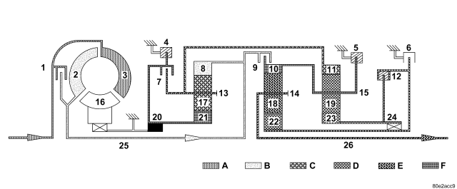
| 1 - TORQUE CONVERTER LOCK-UP CLUTCH |
14 - CENTER PLANETARY CARRIER |
| 2 - TORQUE CONVERTER TURBINE |
15 - REAR PLANETARY CARRIER |
| 3 - TORQUE CONVERTER IMPELLER |
16 - TORQUE CONVERTER STATOR |
| 4 - HOLDING CLUTCH B1 |
17 - FRONT PLANETARY PINION GEARS |
| 5 - HOLDING CLUTCH B3 |
18 - CENTER PLANETARY PINION GEARS |
| 6 - HOLDING CLUTCH B2 |
19 - REAR PLANETARY PINION GEARS |
| 7 - DRIVING CLUTCH K1 |
20 - FREEWHEELING CLUTCH F1 |
| 8 - FRONT PLANETARY ANNULUS GEAR |
21 - FRONT PLANETARY SUN GEAR |
| 9 - DRIVING CLUTCH K2 |
22 - CENTER PLANETARY SUN GEAR |
| 10 - CENTER PLANETARY ANNULUS GEAR |
23 - REAR PLANETARY SUN GEAR |
| 11 - REAR PLANETARY ANNULUS GEAR |
24 - FREEWHEELING CLUTCH F2 |
| 12 - DRIVING CLUTCH K3 |
25 - INPUT SHAFT |
| 13 - FRONT PLANETARY CARRIER |
26 - OUTPUT SHAFT |
| A - ENGINE SPEED |
D - SECOND GEAR RATIO |
| B - TRANSMISSION INPUT SPEED |
E - THIRD GEAR RATIO |
| C - FIRST GEAR RATIO |
F - FIXED PARTS |
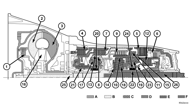
| 1 - TORQUE CONVERTER LOCK-UP CLUTCH |
14 - CENTER PLANETARY CARRIER |
| 2 - TORQUE CONVERTER TURBINE |
15 - REAR PLANETARY CARRIER |
| 3 - TORQUE CONVERTER IMPELLER |
16 - TORQUE CONVERTER STATOR |
| 4 - HOLDING CLUTCH B1 |
17 - FRONT PLANETARY PINION GEARS |
| 5 - HOLDING CLUTCH B3 |
18 - CENTER PLANETARY PINION GEARS |
| 6 - HOLDING CLUTCH B2 |
19 - REAR PLANETARY PINION GEARS |
| 7 - DRIVING CLUTCH K1 |
20 - FREEWHEELING CLUTCH F1 |
| 8 - FRONT PLANETARY ANNULUS GEAR |
21 - FRONT PLANETARY SUN GEAR |
| 9 - DRIVING CLUTCH K2 |
22 - CENTER PLANETARY SUN GEAR |
| 10 - CENTER PLANETARY ANNULUS GEAR |
23 - REAR PLANETARY SUN GEAR |
| 11 - REAR PLANETARY ANNULUS GEAR |
24 - FREEWHEELING CLUTCH F2 |
| 12 - DRIVING CLUTCH K3 |
25 - INPUT SHAFT |
| 13 - FRONT PLANETARY CARRIER |
26 - OUTPUT SHAFT |
| A - ENGINE SPEED |
D - SECOND GEAR RATIO |
| B - TRANSMISSION INPUT SPEED |
E - THIRD GEAR RATIO |
| C - FIRST GEAR RATIO |
F - FIXED PARTS |
Torque from the torque converter is increased via the input shaft (25) and all three planetary gearsets and transferred with reversed direction of rotation to the output shaft (26).
Front Planetary Gear Set
The annulus gear (8) is driven by the input shaft (25). The sun gear (21) is held against the housing by the locked freewheel F1 (20) during acceleration and via the engaged multiple-disc holding clutch B1 (4) during deceleration. The planetary pinion gears (17) turn on the fixed sun gear (21) and increase the torque from the annulus gear (8) to the planetary carrier (13). The planetary carrier (13) moves at a reduced speed in the running direction of the engine.
Rear Planetary Gear Set
The planetary carrier (15) is held against the housing by the engaged multiple-disc holding clutch B3 (5). The annulus gear (11) turns at a reduced speed due to the mechanical connection to the front planetary carrier (13). The planetary gears (19) turn between the annulus gear (11) and the sun gear (23). The direction is reversed by the held planetary carrier (15) so that the sun gear (23) turns in the opposite direction to the running direction of the engine.
Center Planetary Gear Set
The annulus gear (10) is held against the housing by the multiple-disc holding clutch B3 (5) via the mechanical connection to the planetary carrier (15). The sun gear (22) turns backwards due to the engaged multiple-disc clutch K3 (12). The planetary gears (18) turn on the fixed annulus gear (10) and increase the torque from the sun gear (22) to the planetary carrier (14). The output shaft (26) connected to the planetary carrier (14) turns at a reduced speed in the opposite direction to the running direction of the engine.
REVERSE GEAR POWERFLOW - LIMP IN or 4WD LOW RANGE
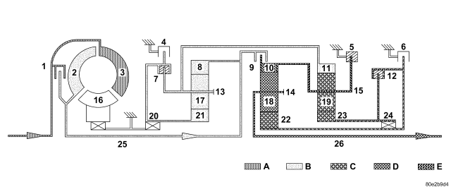
| 1 - TORQUE CONVERTER LOCK-UP CLUTCH |
14 - CENTER PLANETARY CARRIER |
| 2 - TORQUE CONVERTER TURBINE |
15 - REAR PLANETARY CARRIER |
| 3 - TORQUE CONVERTER IMPELLER |
16 - TORQUE CONVERTER STATOR |
| 4 - HOLDING CLUTCH B1 |
17 - FRONT PLANETARY PINION GEARS |
| 5 - HOLDING CLUTCH B3 |
18 - CENTER PLANETARY PINION GEARS |
| 6 - HOLDING CLUTCH B2 |
19 - REAR PLANETARY PINION GEARS |
| 7 - DRIVING CLUTCH K1 |
20 - FREEWHEELING CLUTCH F1 |
| 8 - FRONT PLANETARY ANNULUS GEAR |
21 - FRONT PLANETARY SUN GEAR |
| 9 - DRIVING CLUTCH K2 |
22 - CENTER PLANETARY SUN GEAR |
| 10 - CENTER PLANETARY ANNULUS GEAR |
23 - REAR PLANETARY SUN GEAR |
| 11 - REAR PLANETARY ANNULUS GEAR |
24 - FREEWHEELING CLUTCH F2 |
| 12 - DRIVING CLUTCH K3 |
25 - INPUT SHAFT |
| 13 - FRONT PLANETARY CARRIER |
26 - OUTPUT SHAFT |
| A - ENGINE SPEED |
D - SECOND GEAR RATIO |
| B - TRANSMISSION INPUT SPEED |
E - FIXED PARTS |
| C - FIRST GEAR RATIO |
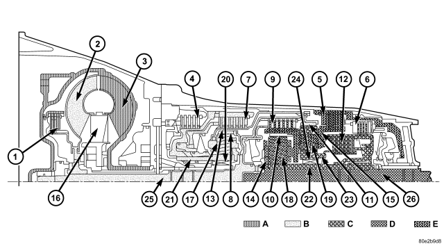
| 1 - TORQUE CONVERTER LOCK-UP CLUTCH |
14 - CENTER PLANETARY CARRIER |
| 2 - TORQUE CONVERTER TURBINE |
15 - REAR PLANETARY CARRIER |
| 3 - TORQUE CONVERTER IMPELLER |
16 - TORQUE CONVERTER STATOR |
| 4 - HOLDING CLUTCH B1 |
17 - FRONT PLANETARY PINION GEARS |
| 5 - HOLDING CLUTCH B3 |
18 - CENTER PLANETARY PINION GEARS |
| 6 - HOLDING CLUTCH B2 |
19 - REAR PLANETARY PINION GEARS |
| 7 - DRIVING CLUTCH K1 |
20 - FREEWHEELING CLUTCH F1 |
| 8 - FRONT PLANETARY ANNULUS GEAR |
21 - FRONT PLANETARY SUN GEAR |
| 9 - DRIVING CLUTCH K2 |
22 - CENTER PLANETARY SUN GEAR |
| 10 - CENTER PLANETARY ANNULUS GEAR |
23 - REAR PLANETARY SUN GEAR |
| 11 - REAR PLANETARY ANNULUS GEAR |
24 - FREEWHEELING CLUTCH F2 |
| 12 - DRIVING CLUTCH K3 |
25 - INPUT SHAFT |
| 13 - FRONT PLANETARY CARRIER |
26 - OUTPUT SHAFT |
| A - ENGINE SPEED |
D - SECOND GEAR RATIO |
| B - TRANSMISSION INPUT SPEED |
E - FIXED PARTS |
| C - FIRST GEAR RATIO |
Torque from the torque converter is increased via the input shaft (25) and all three planetary gearsets and transferred with reversed direction of rotation to the output shaft (26) and .
Front Planetary Gear Set
The clutch K1 (7) is shifted. The planetary carrier (13) and sun gear (21) are connected to each other as a result. The annulus gear (8) is driven via the input shaft (25). The planetary gear set is locked and turns as a unit.
Rear Planetary Gear Set
The planetary carrier (15) is held against the housing by the engaged multiple-disc holding clutch B3 (5). The annulus gear (11) turns at a reduced speed due to the mechanical connection to the front planetary carrier (13). The planetary pinion gears (19) turn between the annulus gear (11) and the sun gear (23). The direction is reversed by the held planetary carrier (15) so that the sun gear (23) turns in the opposite direction to the running direction of the engine.
Center Planetary Gear Set
The annulus gear (10) is held against the housing by the multiple-disc holding clutch B3 (5) via the mechanical connection to the planetary carrier (15). The sun gear (22) turns backwards due to the engaged multiple-disc clutch K3 (12). The planetary gears (18) turn on the fixed annulus gear (10) and increase the torque from the sun gear (22) to the planetary carrier (14). The output shaft (26) connected to the planetary carrier (14) turns at a reduced speed in the opposite direction to the running direction of the engine.
SHIFT GROUPS/ SHIFT SEQUENCE
1-2 Shift - First Gear Engaged
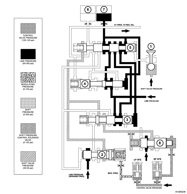
| 1 - 1-2/4-5 SHIFT SOLENOID |
5 - 1-2/4-5 COMMAND VALVE |
| 2 - 1-2/4-5 OVERLAP VALVE |
6 - DRIVING CLUTCH K1 |
| 3 - 1-2/4-5 SHIFT PRESSURE SHIFT VALVE |
7 - HOLDING CLUTCH B1 |
| 4 - 1-2/4-5 HOLDING PRESSURE SHIFT VALVE |
8 - SHIFT PRESSURE REGULATING VALVE |
The end face of the command valve (5) is kept unpressurized via the solenoid valve for 1-2 and 4-5 shift (1). Because of the holding pressure shift valve (4), the working pressure (p-A) is present at the multiple-disc holding clutch B1 (7). Clutch K1 (6) is unpressurized.
Shift Phase - 1-2 Shift Phase 1
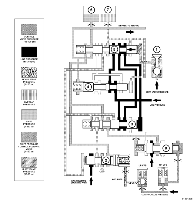
| 1 - 1-2/4-5 SHIFT SOLENOID |
5 - 1-2/4-5 COMMAND VALVE |
| 2 - 1-2/4-5 OVERLAP VALVE |
6 - DRIVING CLUTCH K1 |
| 3 - 1-2/4-5 SHIFT PRESSURE SHIFT VALVE |
7 - HOLDING CLUTCH B1 |
| 4 - 1-2/4-5 HOLDING PRESSURE SHIFT VALVE |
8 - SHIFT PRESSURE REGULATING VALVE |
When the 1-2 and 4-5 shift solenoid valve (1) is turned on, the shift valve pressure (p-SV) is directed onto the end face of the command valve (5). The command valve is moved and the shift pressure (p-S) coming from the shift pressure shift valve (3) is directed via the command valve (5) onto clutch K1 (6).
Simultaneously the clutch B1 (7) is subjected to overlap pressure by the overlap regulating valve (2). The pressure in the clutch B1 (7) as it disengages is controlled during the shift phase depending on engine load by the modulating pressure and the applying clutch pressure (the shift pressure in clutch K1). The controlled pressure in clutch B1 (7) is inversely proportional to the capacity of the clutch being engaged. The rising shift pressure (p-S) at clutch K1 (6) acts on the annular face of the overlap regulating valve (2) and reduces the overlap pressure regulated by the overlap regulating valve (2). When a corresponding pressure level is reached at the holding pressure shift valve (4), this valve switches over.
Shift Phase - 1-2 Shift Phase 2
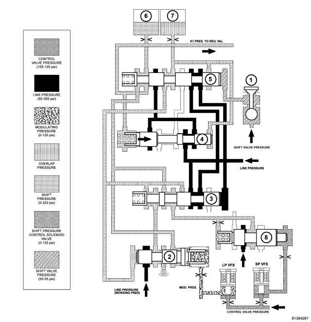
| 1 - 1-2/4-5 SHIFT SOLENOID |
5 - 1-2/4-5 COMMAND VALVE |
| 2 - 1-2/4-5 OVERLAP VALVE |
6 - DRIVING CLUTCH K1 |
| 3 - 1-2/4-5 SHIFT PRESSURE SHIFT VALVE |
7 - HOLDING CLUTCH B1 |
| 4 - 1-2/4-5 HOLDING PRESSURE SHIFT VALVE |
8 - SHIFT PRESSURE REGULATING VALVE |
The B1 (7) pressure acting on the end face of the shift pressure shift valve (3) is replaced by the working pressure (p-A). The shift pressure is also routed to the spring end of the holding valve (4) and the holding valve downshifts. The line pressure is then routed to the command valve (5).
Second Gear Engaged
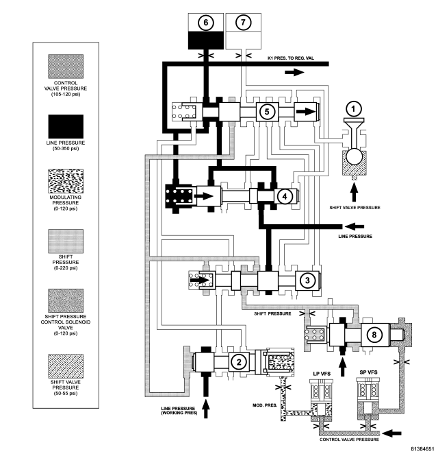
| 1 - 1-2/4-5 SHIFT SOLENOID |
5 - 1-2/4-5 COMMAND VALVE |
| 2 - 1-2/4-5 OVERLAP VALVE |
6 - DRIVING CLUTCH K1 |
| 3 - 1-2/4-5 SHIFT PRESSURE SHIFT VALVE |
7 - HOLDING CLUTCH B1 |
| 4 - 1-2/4-5 HOLDING PRESSURE SHIFT VALVE |
8 - SHIFT PRESSURE REGULATING VALVE |
After the gearchange is complete, the pressure on the end face of the command valve (5) is reduced via the 1-2 and 4-5 shift solenoid valve (1), and the command valve (5) is pushed back to its basic position. Via the holding pressure shift valve (4) the working pressure (p-A) now passes via the command valve (5) to clutch K1 (6). The multiple-disc holding clutch B1 (7) is deactivated (unpressurized). The spring of the shift pressure shift valve (3) pushes the valve back to its basic position.
Shift Phase - 2-1 Shift Phase 1
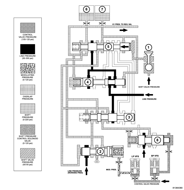
| 1 - 1-2/4-5 SHIFT SOLENOID |
5 - 1-2/4-5 COMMAND VALVE |
| 2 - 1-2/4-5 OVERLAP VALVE |
6 - DRIVING CLUTCH K1 |
| 3 - 1-2/4-5 SHIFT PRESSURE SHIFT VALVE |
7 - HOLDING CLUTCH B1 |
| 4 - 1-2/4-5 HOLDING PRESSURE SHIFT VALVE |
8 - SHIFT PRESSURE REGULATING VALVE |
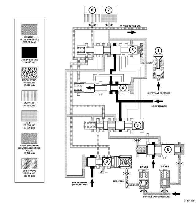
The 1-2/4-5 shift solenoid (1) is turned ON to apply shift pressure (p-S) to the end face of the 1-2/4-5 command valve (5). This allows the command valve to up-shift and the shift pressure coming from the 1-2/4-5 shift valve (3) is routed to the holding clutch B1 (7) via the command valve.
Simultaneously, the pressure in the releasing clutch, K1 (6), is regulated at the 1-2/4-5 overlap valve (2). The pressure in the K1 clutch as it disengages is controlled during the shift phase depending on engine load, via the modulating pressure (p-MOD), and the shift pressure in clutch B1 (7). The increasing shift pressure in clutch B1, which also acts on the end face of the overlap valve, reduces the overlap pressure.
Shift Phase - 2-1 Shift Phase 2
| 1 - 1-2/4-5 SHIFT SOLENOID |
5 - 1-2/4-5 COMMAND VALVE |
| 2 - 1-2/4-5 OVERLAP VALVE |
6 - DRIVING CLUTCH K1 |
| 3 - 1-2/4-5 SHIFT PRESSURE SHIFT VALVE |
7 - HOLDING CLUTCH B1 |
| 4 - 1-2/4-5 HOLDING PRESSURE SHIFT VALVE |
8 - SHIFT PRESSURE REGULATING VALVE |
The pressure in clutch B1 (7) acting on the end face of the 1-2/4-5 holding valve (4) forces the valve to up-shift against the spring pressure and allows line pressure (p-A) to pass through the command valve (5).
2-1 Shift - First Gear Engaged
| 1 - 1-2/4-5 SHIFT SOLENOID |
5 - 1-2/4-5 COMMAND VALVE |
| 2 - 1-2/4-5 OVERLAP VALVE |
6 - DRIVING CLUTCH K1 |
| 3 - 1-2/4-5 SHIFT PRESSURE SHIFT VALVE |
7 - HOLDING CLUTCH B1 |
| 4 - 1-2/4-5 HOLDING PRESSURE SHIFT VALVE |
8 - SHIFT PRESSURE REGULATING VALVE |
After the gear change is complete, the 1-2/4-5 shift solenoid (1) is turned off. This reduces the pressure on the end face of the 1-2/4-5 command valve (5) to 0 psi and the spring pressure downshifts the valve to its initial position. The line pressure (p-A) is switched to the holding clutch B1 (7) and the end face of the holding valve by the downshifted command valve. The upshifted holding valve also allows the remaining pressure in clutch K1 (6) to be vented.
Gear Shift N to D (1st gear) - Engine Started
| 1 - HOLDING CLUTCH B1 |
11 - PRESSURE HOLDING VALVE |
| 2 - DRIVING CLUTCH K1 |
12 - 3-4 HOLDING PRESSURE SHIFT VALVE |
| 3 - HOLDING CLUTCH B3 |
13 - 3-4 COMMAND VALVE |
| 4 - DRIVING CLUTCH K3 |
14 - 3-4 SHIFT PRESSURE SHIFT VALVE |
| 5 - HOLDING CLUTCH B2 PISTON |
15 - 3-4 OVERLAP REGULATING VALVE |
| 6 - HOLDING CLUTCH B2 PISTON OPPOSING FACE |
16 - BALL VALVE |
| 7 - SHIFT PRESSURE REGULATING SOLENOID |
17 - 1-2/4-5 COMMAND VALVE |
| 8 - SHIFT PRESSURE REGULATING VALVE |
18 - 1-2/4-5 COMMAND VALVE |
| 9 - SHIFT VALVE B2 |
19 - BALL VALVE |
| 10 - 3-4 SHIFT SOLENOID |
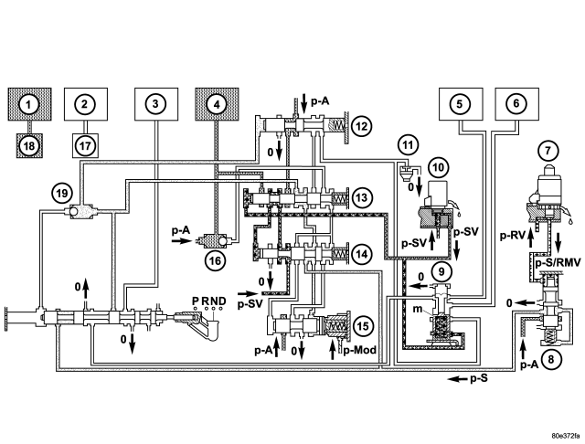
With the engine started and the gearshift lever in the NEUTRAL or PARK positions, holding clutch B1 (1) and driving clutch K3 (4) are applied and the various valves in the 1-2/4-5 shift group are positioned to apply pressure to the holding clutch B2.
Activation Sequence
| 1 - HOLDING CLUTCH B1 |
11 - PRESSURE HOLDING VALVE |
| 2 - DRIVING CLUTCH K1 |
12 - 3-4 HOLDING PRESSURE SHIFT VALVE |
| 3 - HOLDING CLUTCH B3 |
13 - 3-4 COMMAND VALVE |
| 4 - DRIVING CLUTCH K3 |
14 - 3-4 SHIFT PRESSURE SHIFT VALVE |
| 5 - HOLDING CLUTCH B2 PISTON |
15 - 3-4 OVERLAP REGULATING VALVE |
| 6 - HOLDING CLUTCH B2 PISTON OPPOSING FACE |
16 - BALL VALVE |
| 7 - SHIFT PRESSURE REGULATING SOLENOID |
17 - 1-2/4-5 COMMAND VALVE |
| 8 - SHIFT PRESSURE REGULATING VALVE |
18 - 1-2/4-5 COMMAND VALVE |
| 9 - SHIFT VALVE B2 |
19 - BALL VALVE |
| 10 - 3-4 SHIFT SOLENOID |
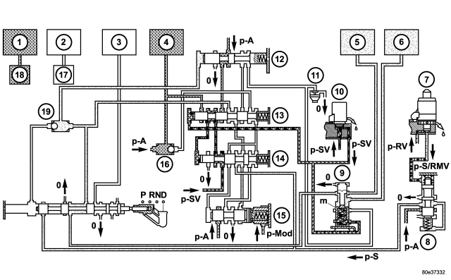
The selector valve opens the shift pressure (p-S) feed connection from the ball valve (19) with the shift valve B2 (9). With the shift valve B2 (9) in the upper position, shift pressure (p-S) travels behind the piston B2 (5) and simultaneously to the opposing face of the piston B2 (6). The multiple-disc holding clutch B2 begins to close.
The pressure on the opposing face of the piston B2 (6) ensures a soft activation of the multiple-disc holding clutch B2.
First Gear Engaged
| 1 - HOLDING CLUTCH B1 |
11 - PRESSURE HOLDING VALVE |
| 2 - DRIVING CLUTCH K1 |
12 - 3-4 HOLDING PRESSURE SHIFT VALVE |
| 3 - HOLDING CLUTCH B3 |
13 - 3-4 COMMAND VALVE |
| 4 - DRIVING CLUTCH K3 |
14 - 3-4 SHIFT PRESSURE SHIFT VALVE |
| 5 - HOLDING CLUTCH B2 PISTON |
15 - 3-4 OVERLAP REGULATING VALVE |
| 6 - HOLDING CLUTCH B2 PISTON OPPOSING FACE |
16 - BALL VALVE |
| 7 - SHIFT PRESSURE REGULATING SOLENOID |
17 - 1-2/4-5 COMMAND VALVE |
| 8 - SHIFT PRESSURE REGULATING VALVE |
18 - 1-2/4-5 COMMAND VALVE |
| 9 - SHIFT VALVE B2 |
19 - BALL VALVE |
| 10 - 3-4 SHIFT SOLENOID |
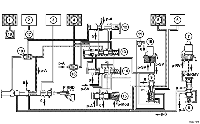
The TCM monitors the activation sequence via the speed of the input shaft, which slows down as the frictional connection in the multiple-disc holding clutch increases. When the speed drops to the specified level, the TCM shuts off the power to the 3-4 shift solenoid valve (10). The spring chamber of the shift valve B2 (9) is depressurized and switches downwards. This connects the line to the opposing face of the piston B2 (6) with the pressure holding valve (11). The pressure on the opposing face of the piston B2 (6) drops to a residual pressure.
The working pressure (p-A) is formed and travels via the 2-3 holding pressure shift valve, the 2-3 command valve and the ball valve (16) to multi-plate clutch K3 (4) and via the 3-4 command valve (13) to the end face of the 3-4 shift pressure shift valve (14). The 3-4 shift pressure shift valve (14) is moved against the force of the spring towards the right. At the same time the 3-4 solenoid valve (10) is energized. This allows shift valve pressure (p-SV) to enter the spring chamber of the shift valve B2 (9) and to reach the end face of the 3-4 command valve (13). The shift valve B2 (9) is held in the upper position and the 3-4 command valve (13) switches towards the right. At the end face of the 3-4 shift pressure shift valve (14) the working pressure (p-A) is replaced by shift valve pressure (p-SV).
The 3-4 command valve (13) moves to the left. Working pressure (p-A) travels via the holding pressure shift valve (12) and the 3-4 command valve (13) to the piston of multiple-disc holding clutch B2 (5).
STANDARD PROCEDURE - ALUMINUM THREAD REPAIR
Damaged or worn threads in the aluminum transmission case and valve body can be repaired by the use of Heli-Coils™, or equivalent. This repair consists of drilling out the worn-out damaged threads. Then tap the hole with a special Heli-Coil™ tap, or equivalent, and installing a Heli-Coil™ insert, or equivalent, into the hole. This brings the hole back to its original thread size.
Heli-Coil™, or equivalent, tools and inserts are readily available from most automotive parts suppliers.
REMOVAL
NOTE: If the transmission is being reconditioned (clutch/seal replacement) or replaced, it is necessary to perform the TCM Adaptation Procedure using the scan tool (Refer to 8 - ELECTRICAL/ELECTRONIC CONTROL MODULES/TRANSMISSION CONTROL MODULE - STANDARD PROCEDURE).
1. Disconnect the negative battery cable.
2. Raise and support the vehicle.
3. Remove the propeller shafts. (Refer to 3 - DIFFERENTIAL & DRIVELINE/PROPELLER SHAFT/PROPELLER SHAFT - REMOVAL)
4. Remove the bolts holding the starter motor to the transmission. (Refer to 8 - ELECTRICAL/STARTING/STARTER MOTOR - REMOVAL)
5. Remove the starter from the transmission starter pocket and safely relocate.
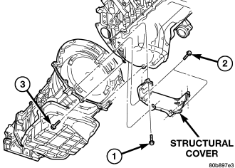
6. Remove the bolts (1, 2, 3) holding the structural cover to the transmission and engine.
7. Remove the structural cover from the vehicle.
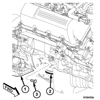
8. For gas engines, rotate crankshaft in clockwise direction until converter bolts (3) are accessible. Then remove bolts (3) one at a time. Rotate crankshaft with socket wrench on dampener bolt.
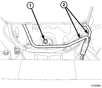
9. For diesel engines, rotate crankshaft in clockwise direction until converter bolts (1) are accessible. Then remove bolts (1) one at a time. Rotate crankshaft with socket wrench on dampener bolt.
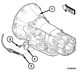
10. Disconnect the gearshift cable (3) from the transmission manual valve lever.
11. Remove the shift cable (3) from the gearshift cable bracket (4).
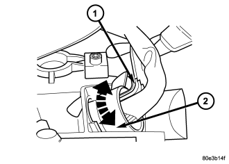
12. Disconnect 13-pin plug connector (1). Turn bayonet lock of the adapter plug (2) anti-clockwise.
13. Remove the 13-pin connector (1) from the transmission.
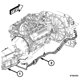
14. Disconnect transmission fluid cooler lines (2) at transmission (1).
15. Disconnect the transmission vent hose from the transmission.
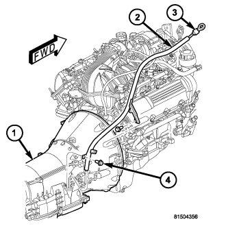
16. Remove the bolts (4) holding the transmission fill tube (2) to the transmission (1).
17. Support rear of engine with safety stand or jack.
18. Raise transmission slightly with service jack to relieve load on crossmember and supports.
19. Remove bolts securing rear support and cushion to transmission crossmember.
20. Remove bolts attaching crossmember to frame and remove crossmember.
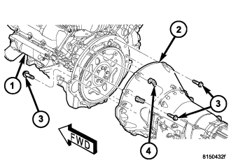
21. Remove all remaining bolts (3) holding the engine (1) to the transmission (2). Note the location of any wiring harness clips (4).
22. Carefully work transmission and torque converter assembly rearward off engine block dowels.
23. Hold torque converter in place during transmission removal.
24. Lower transmission and remove assembly from under the vehicle.
25. To remove torque converter, carefully slide torque converter out of the transmission.
DISASSEMBLY
NOTE: If the transmission is being reconditioned (clutch/seal replacement) or replaced, it is necessary to perform the TCM Adaptation Procedure using the scan tool (Refer to 8 - ELECTRICAL/ELECTRONIC CONTROL MODULES/TRANSMISSION CONTROL MODULE - STANDARD PROCEDURE).
NOTE: Tag all clutch pack assemblies, as they are removed, for reassembly identification.
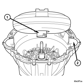
1. Remove the torque converter (1).
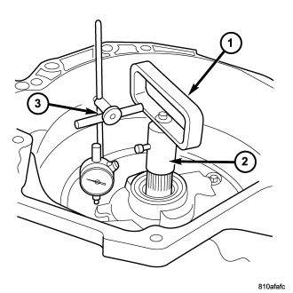
2. Place transmission in a vertical position.
3. Measure input shaft end play as follows:
a. Attach Adapter 8266-18 (2) to Handle 8266-8 (1).
b. Attach dial indicator C-3339 (3) to Handle 8266-8 (1).
c. Install the assembled tool onto the input shaft of the transmission and tighten the retaining screw on Adapter 8266-18 (2) to secure it to the input shaft.
d. Position the dial indicator plunger against a flat spot on the oil pump and zero the dial indicator.
e. Move the input shaft in and out. Record the maximum travel for assembly reference.
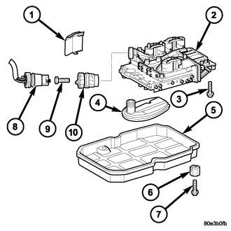
4. Loosen adapter plug bolt (9) and remove from the adapter plug (10) from the transmission housing.
5. Detach oil pan (5).
6. Remove oil filter (4).
7. Unscrew Torx socket bolts (3) and remove electrohydraulic unit (2).
8. Place the transmission in PARK to prepare for the removal of the output shaft nut.
9. Remove the nut, with a 30 mm 12 point socket, holding the propeller shaft flange to the output shaft and remove the flange.
10. Remove the transmission rear oil seal with a suitable slide hammer and screw.
11. Remove the transmission output shaft washer. Be sure to tag the washer since it is very similar to the geartrain end-play shim and they must not be interchanged.
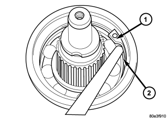
12. Remove the transmission rear output shaft bearing retaining ring (1).
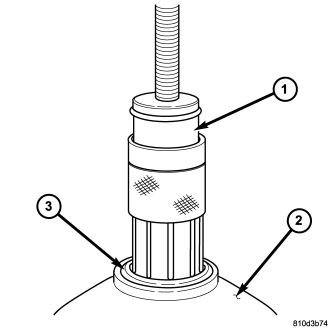
13. Position Bearing Remover 9082 (1) over the inner race of the output shaft bearing (3).
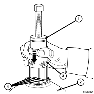
NOTE: Due to production variations in the bearing, it may not be possible to slide the collar fully downward. It is only necessary to slide the collar down far enough that the fingers securely grasp the inner bearing race.
14. Slide the collar (3) on the Bearing Remover 9082 (1) downward over the fingers (4) of the tool.
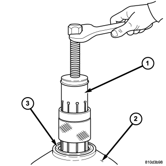
15. Remove the output shaft bearing (3).
16. Remove the geartrain end-play shim from the output shaft. Be sure to tag the shim since it is very similar to the output shaft washer and they must not be interchanged.
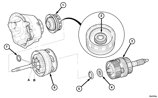
17. Remove the bolts holding the transmission housing to the converter housing from inside the converter housing.
18. Stand the transmission upright on the converter housing.
19. Remove the remaining bolts holding the transmission housing to the converter housing.
20. Remove the transmission housing from the converter housing.
21. Remove output shaft with center and rear gear set and clutch K3 (3).
22. Remove thrust needle bearing (4) and thrust washer (5).
23. Remove input shaft with clutch K2 and front gear set (6).
24. Remove clutch K1 (1).
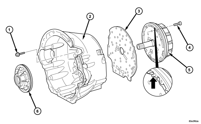
| Remove Holding Clutch B1 and Oil Pump |
| 1 - BOLTS - M6X32 | 4 - BOLTS - M8X35 |
| 2 - CONVERTER HOUSING | 5 - HOLDING CLUTCH B1 |
| 3 - INTERMEDIATE PLATE | 6 - OIL PUMP |
25. Unscrew Torx socket bolts (4) and remove oil pump (6). Screw two opposed bolts into the oil pump housing and press the oil pump out of the converter housing by applying light blows with a plastic hammer.
26. Remove and discard the torque converter hub seal and the oil pump outer o-ring seal from the oil pump.
27. Unscrew Torx socket bolts (1) and remove multiple-disc holding clutch B1 (5) from converter housing. Screw two opposed bolts into the multiple-disc holding clutch B1 (5) and separate from the converter housing by applying light blows with a plastic hammer.
28. Detach intermediate plate (3) from converter housing (2).
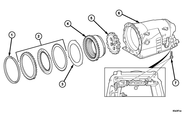
29. Remove multiple-disc pack B3 (2) and spring washer (3) by removing snap-ring (1) in transmission housing. To facilitate removal of the snap-ring (1), compress the multiple-disc pack B3 (2). Note which clutch disc is removed just prior to the spring washer (3) for re-assembly. If the clutch discs are re-used, this disc must be returned to its original position on top of the spring washer.
30. Unscrew Torx socket bolts (7).
31. Remove multiple-disc holding clutch B2 (4) from transmission housing. The externally toothed disc carrier for multiple-disc holding clutch B2 is also the piston for multiple-disc holding clutch B3.
32. Remove parking lock gear (5).
ASSEMBLY
NOTE: If the transmission is being reconditioned (clutch/seal replacement) or replaced, it is necessary to perform the TCM Adaptation Procedure using the scan tool (Refer to 8 - ELECTRICAL/ELECTRONIC CONTROL MODULES/TRANSMISSION CONTROL MODULE - STANDARD PROCEDURE).
1. Insert parking lock gear (5).
2. Install multiple-disc holding clutch B2 (4) in transmission housing (6).
3. Screw in both Torx socket bolts (7). Tighten the bolts to 16 N·m (141 in.lbs.).
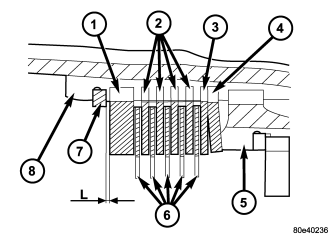
NOTE: During the measurement the snap ring (7) must contact the upper bearing surface of the groove in the outer multiple-disc carrier (8).
NOTE: Pay attention to sequence of discs. If the original clutch discs are reused, be sure to return the disc identified on disassembly as belonging on top of the spring washer (4) to its original location. Place new friction multiple-discs in ATF fluid for one hour before installing.
CAUTION: Apply only light pressure (less than 10 N (3 lbs.) of force) to the clutch pack when measuring the clutch clearance with the feeler gauge. Applying excessive force to the clutch will give an incorrect reading and lead to a transmission failure.
4. Insert and measure spring washer (4) and multiple-disc pack B3 (2, 6).
a. Put multiple-discs for multiple-disc holding clutch B3 together in the sequence shown in the illustration and insert individually.
b. Using a feeler gauge, determine the play "L" at three points between the snap ring (7) and outer multiple-disc (1). B3 clutch clearance should be 1.0-1.4 mm (0.039-0.055 in.). Adjust the clearance as necessary.
c. Adjust with snap-ring (7), if necessary. Snap-rings are available in thicknesses of 3.2 mm (0.126 in.), 3.5 mm (0.138 in.), 3.8 mm (0.150 in.), 4.1 mm (0.162 in.), 4.4 mm (0.173 in.), and 4.7 mm (0.185 in.).
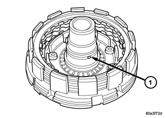
5. Check that the K1 clutch feed hole (1) in the inner hub of clutch B1 is free before installing clutch B1.
6. Place intermediate plate (3) on converter housing (2) and align.
NOTE: The intermediate plate can generally be used several times. The plate must not be coated with additional sealant
7. Install the holding clutch B1 (5) onto the converter housing and intermediate plate. Installed position of clutch B1 in relation to converter housing is specified by a plain dowel pin in clutch B1 (arrow).
8. Install the bolts to hold clutch B1 (5) to the converter housing.
9. Securely tighten multiple-disc holding clutch B1 (5) on converter housing (2) to 10 N·m (89 in.lbs.).
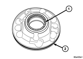
10. Install new torque converter hub seal (1) into the oil pump using Seal Installer 8902A.
11. Install new oil pump outer o-ring seal onto oil pump.
12. Install oil pump (6) and securely tighten. Tighten the oil pump bolts to 20 N·m (177 in.lbs.).
13. Using grease, insert sealing rings (7) in the groove so that the joint remains together.
14. Install the K1 (1) clutch onto the B1 clutch.
15. Install input shaft with clutch K2 (6) and front gear set (1).
16. Install front washer (5) and thrust needle bearing (4).
NOTE: Insure that the pinion gears are fully seated in the Rear Annulus (Hollow) Gear. If 50% of the pinion gear splines protrude, the Rear Annulus Gear was installed upside down in the K2 Clutch Retainer.
17. Install output shaft with center and rear gear set and clutch K3 (3).
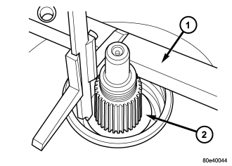
18. Using grease, install both Teflon rings in the groove at the rear of the output shaft so that the joint stays together.
19. Mount transmission housing on converter housing.
20. Screw in Torx socket bolts through the transmission housing into the converter housing. Tighten the bolts to 20 N·m (177 in.lbs.).
NOTE: Verify that there are no nicks or other irregularities in the surface of the transmission case that will cause an inaccurate measurement.
21. Measure end-play between park pawl gear and grooved ball bearing in order to select the proper geartrain end-play shim.
22. Place Gauge Bar 6311 (1) on transmission housing. Using a depth gauge, measure from the gauge bar (1) to the parking lock gear (2).
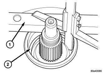
23. Using a depth gauge, measure from the Gauge Bar 6311 (1) to the contact surface of the output shaft bearing (2) in the transmission housing.
24. Subtract the first figure from the second figure to determine the current end-play of the transmission. Select a shim or a combination of two shims such that the end-play will be 0.3-0.5 mm (0.012-0.020 in.). Shims are available in thicknesses of 0.2 mm (0.008 in.), 0.3 mm (0.012 in.), 0.4 mm (0.016 in.), and 0.5 mm (0.020 in.).
25. Install the selected end-play shim.
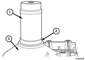
26. Screw in Torx socket bolts through the converter housing into the transmission housing. Tighten the bolts to 20 N·m (177 in.lbs.).
27. Install output shaft bearing (2) in rear transmission housing. Using Bearing Installer 9287 (1), install the output shaft bearing (2) into the transmission housing. The closed side of the plastic cage must point towards the parking lock gear.
28. Install the retaining ring (1). Ensure that the retaining ring is seated correctly in the groove.
29. Check that there is no play between the bearing and the retaining ring using feeler gauge.
30. There must be no play between the retaining ring and the bearing. If the ring cannot be installed, a thinner ring must be used. If there is play between the ring and the bearing, a thicker ring must be installed. Retaining rings are available in thicknesses of 2.0 mm (0.079 in.), 2.1 mm (0.083 in.), and 2.2 mm (0.087 in.).
31. Rotate the transmission so that the bellhousing is pointed upward and ensuring that the output shaft is allowed to move freely.
32. Measure input shaft end-play .
NOTE: If end-play is incorrect, transmission is incorrectly assembled, or the geartrain end-play shim is incorrect. The geartrain end-play shim is selective.
NOTE: If necessary, a combination of shims can be used to achieve the required end-play.
a. Attach Adapter 8266-18 (2) to Handle 8266-8 (1).
b. Attach dial indicator C-3339 (3) to Handle 8266-8 (1).
c. Install the assembled tool onto the input shaft of the transmission and tighten the retaining screw on Adapter 8266-18 to secure it to the input shaft.
d. Position the dial indicator plunger against a flat spot on the oil pump and zero the dial indicator.
e. Move input shaft in and out and record reading. End play should be 0.3-0.5 mm (0.012-0.020 in.). Adjust as necessary.
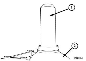
NOTE: The output shaft shim should be 0.3 mm (0.012 in.). If a 0.3 mm (0.012 in.) shim is not available, use a 0.2 mm (0.008 in.) 0.4 mm (0.016 in.) or 0.5 mm (.020 in.) shim.
33. Install the output shaft shim onto the output shaft.
34. Install a new transmission rear seal into the transmission case with Seal Installer 8902A (1).
35. Place the transmission in PARK to prepare for the installation of the output shaft nut.
36. Inspect the seal protector on the rear of the output shaft flange. Replace the seal protector if damaged. the seal protector can be removed using a suitable pry tool and installed with a suitable tube style tool.
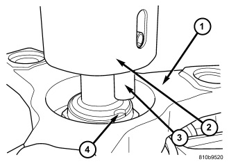
37. Install the propeller shaft flange onto the output shaft and install an new flange nut. Tighten the flange nut, with a 30 mm 12 point socket, to 200 N·m (147.5 ft.lbs.).
38. Place the Staking Tool 9078 (2) and Driver Handle C-4171 onto the output shaft.
39. Rotate the Staking Tool 9078 (2) until the alignment pin (3) engages the output shaft notch (4).
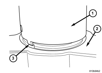
40. Press downward on the staking tool (1) until the staking pin (3) contacts the output shaft nut flange (2).
41. Strike the Driver handle C-4171 with a suitable hammer until the output shaft nut is securely staked to the output shaft.
42. Install electrohydraulic unit (2). Tighten the bolts to 8 N·m (71 in.lbs.).
43. Install oil filter (4).
44. Install oil pan (5). Tighten the bolts to 8 N·m (71 in.lbs.).
45. Install the adapter plug (10). Tighten the bolt (9) to 2.5 N·m ( 22 in. lbs.).
46. Install the torque converter.
INSTALLATION
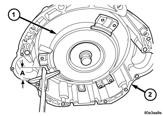
1. Check torque converter hub and hub drive flats for sharp edges burrs, scratches, or nicks. Polish the hub and flats with 320/400 grit paper and crocus cloth if necessary. The hub must be smooth to avoid damaging pump seal at installation.
2. If a replacement transmission is being installed, transfer any components necessary, such as the manual shift lever and shift cable bracket, from the original transmission onto the replacement transmission.
3. Lubricate oil pump seal lip with transmission fluid.
4. Place torque converter in position on transmission.
CAUTION: Do not damage oil pump seal or converter hub while inserting torque converter into the front of the transmission.
5. Align torque converter to oil pump seal opening.
6. Insert torque converter (1) hub into oil pump.
7. While pushing torque converter inward, rotate converter until converter is fully seated in the oil pump gears.
8. Check converter seating with a scale and straightedge. Surface of converter lugs should be at least 19 mm (3/4 in.) to rear of straightedge when converter is fully seated.
9. If necessary, temporarily secure converter with C-clamp attached to the converter housing.
10. Check condition of converter driveplate. Replace the plate if cracked, distorted or damaged. Also be sure transmission dowel pins are seated in engine block and protrude far enough to hold transmission in alignment.
11. Apply a light coating of Mopar® High Temp Grease to the torque converter hub pocket in the rear pocket of the engine's crankshaft.
12. Raise transmission and align the torque converter with the drive plate and the transmission converter housing with the engine block.
13. Move transmission forward. Then raise, lower, or tilt transmission to align the converter housing with the engine block dowels.
14. Carefully work transmission (2) forward and over engine (1) block dowels until converter hub is seated in crankshaft. Verify that no wires, or the transmission vent hose, have become trapped between the engine block and the transmission.
15. Install two bolts (3) to attach the transmission to the engine.
16. Install remaining torque converter housing to engine bolts. Tighten to 39 N·m (29 ft.lbs.).
17. Install rear transmission crossmember. Tighten crossmember to frame bolts to 68 N·m (50 ft.lbs.).
18. Install rear support to transmission. Tighten bolts to 47 N·m (35 ft.lbs.).
19. Lower transmission onto crossmember and install bolts attaching transmission mount to crossmember. Tighten clevis bracket to crossmember bolts to 47 N·m (39 ft.lbs.). Tighten the clevis bracket to rear support bolt to 68 N·m (50 ft.lbs.).
20. Remove engine support fixture.
21. Install the engine to transmission structutral cover. (Refer to 9 - ENGINE/ENGINE BLOCK/STRUCTURAL COVER - INSTALLATION)
22. Connect gearshift cable (3) to the gearshift cable bracket (4) and transmission (1).
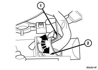
23. Check O-ring on plug connector (1) , and replace if necessary.
24. Install the plug connector (1) into the adapter plug (2). Turn bayonet lock of the adapter plug (2) clockwise to connect plug connector (1).
CAUTION: It is essential that correct length bolts be used to attach the converter to the driveplate. Bolts that are too long will damage the clutch surface inside the converter.
25. For gas engines, install all torque converter-to-driveplate bolts (3) by hand.
26. Verify that the torque converter is pulled flush to the driveplate. Tighten bolts to 42 N·m (31 ft. lbs.).
CAUTION: It is essential that correct length bolts be used to attach the converter to the driveplate. Bolts that are too long will damage the clutch surface inside the converter.
27. For diesel engines, install all torque converter-to-driveplate bolts (1) by hand.
28. Verify that the torque converter is pulled flush to the driveplate. Tighten bolts to 42 N·m (31 ft. lbs.).
29. Install starter motor. (Refer to 8 - ELECTRICAL/STARTING/STARTER MOTOR - INSTALLATION)
30. Install transmission fill tube (2).
31. Connect cooler lines (2) to transmission (1).
32. Install exhaust components.
33. Install transfer case, if necessary. (Refer to 21 - TRANSMISSION/TRANSAXLE/TRANSFER CASE - REMOVAL)
34. Align and connect propeller shafts. (Refer to 3 - DIFFERENTIAL & DRIVELINE/PROPELLER SHAFT/PROPELLER SHAFT - INSTALLATION)
35. Adjust gearshift cable if necessary. (Refer to 21 - TRANSMISSION/AUTOMATIC - NAG1/GEAR SHIFT CABLE - ADJUSTMENTS)
36. Lower vehicle.
37. Connect negative battery cable.
38. Fill transmission with the appropriate fluid (Refer to 21 - TRANSMISSION/AUTOMATIC - NAG1/FILTER - STANDARD PROCEDURE).
39. Verify proper operation.
SCHEMATICS AND DIAGRAMS
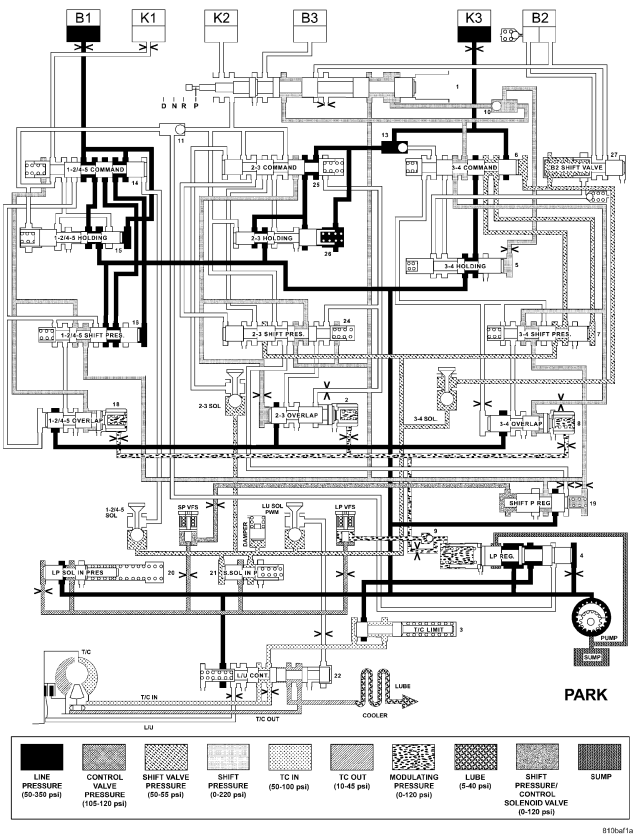
| HYDRAULIC FLOW IN PARK |
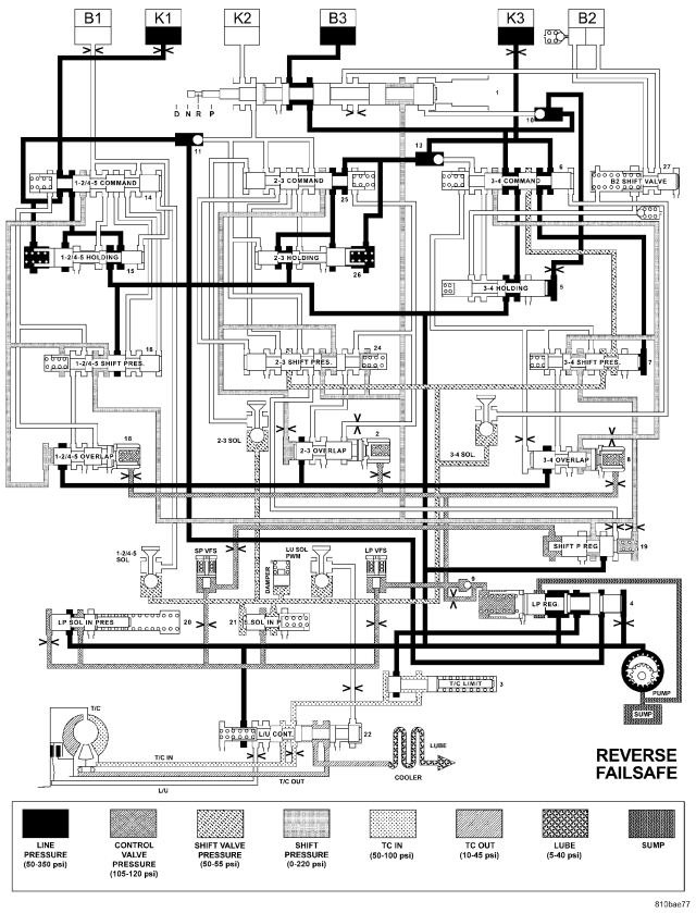
| HYDRAULIC FLOW IN REVERSE - FAILSAFE |
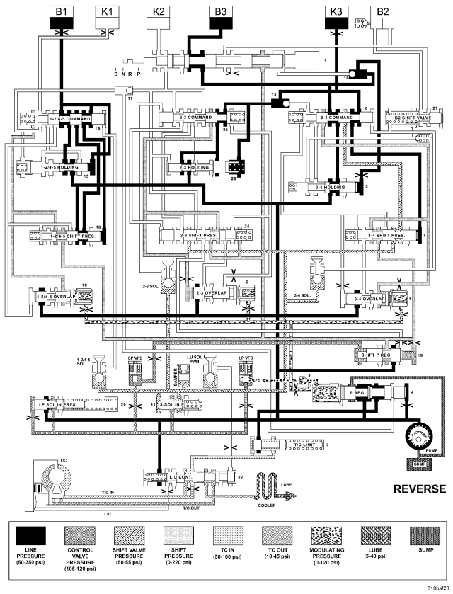
| HYDRAULIC FLOW IN REVERSE |
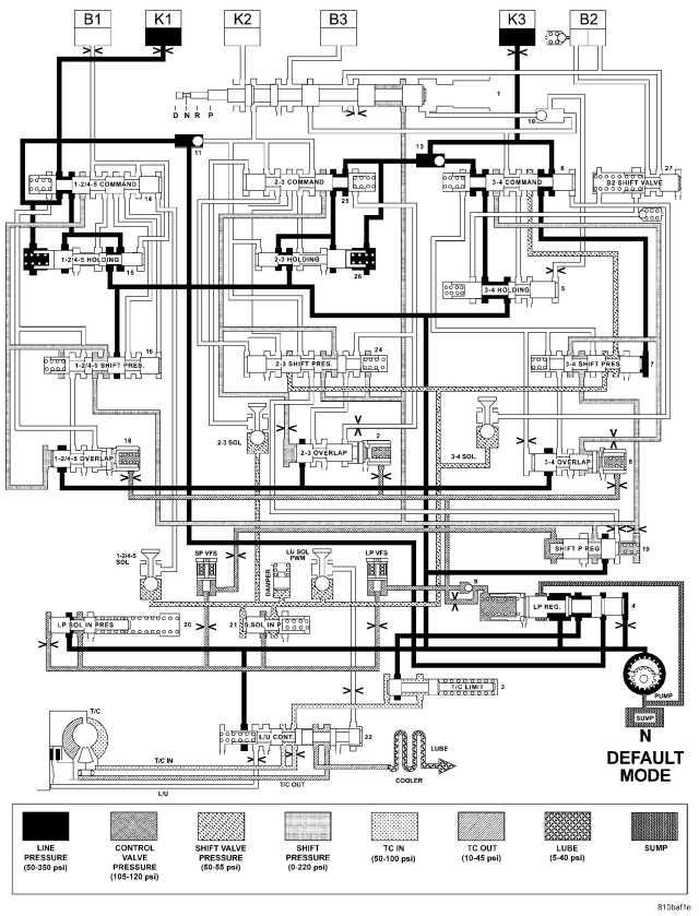
| HYDRAULIC FLOW IN NEUTRAL - DEFAULT |
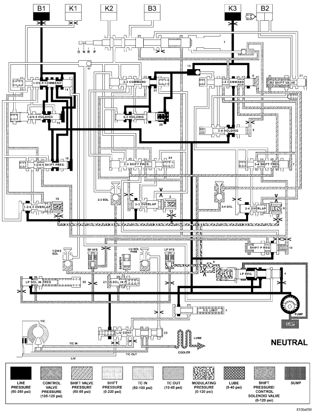
| HYDRAULIC FLOW IN NEUTRAL |
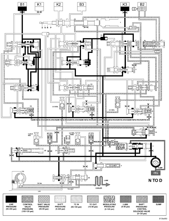
| HYDRAULIC FLOW IN NEUTRAL TO DRIVE TRANSITION |
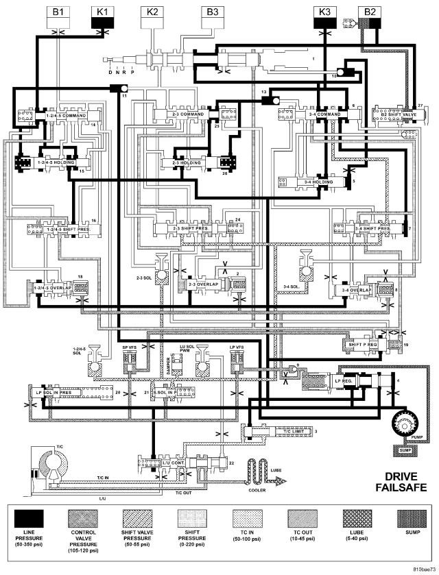
| HYDRAULIC FLOW IN DRIVE - FAILSAFE |
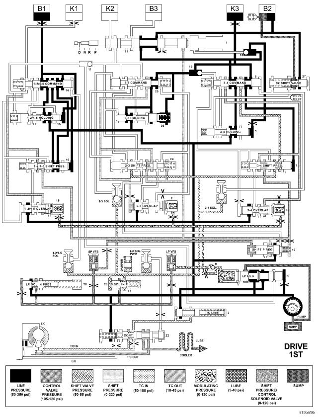
| HYDRAULIC FLOW IN DRIVE - FIRST GEAR |
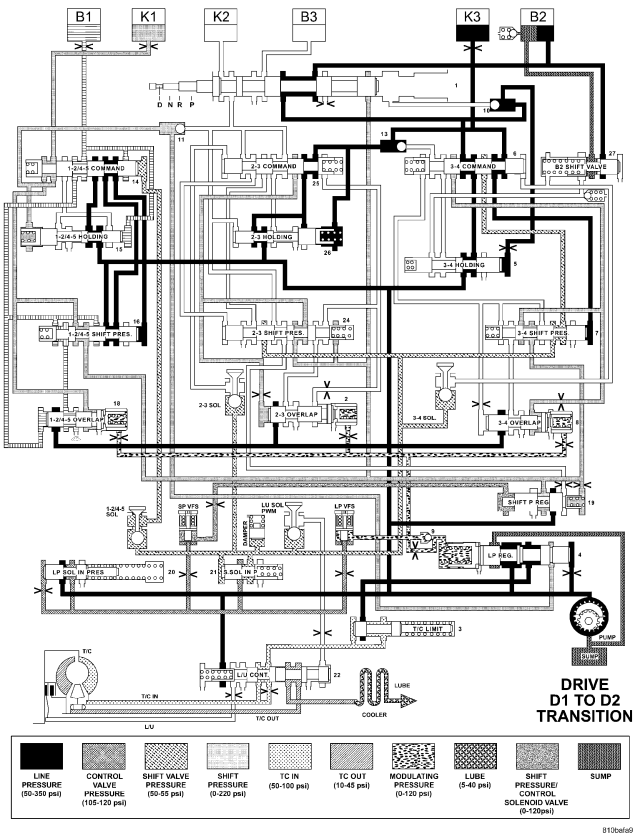
| HYDRAULIC FLOW IN DRIVE - FIRST TO SECOND GEAR TRANSITION |
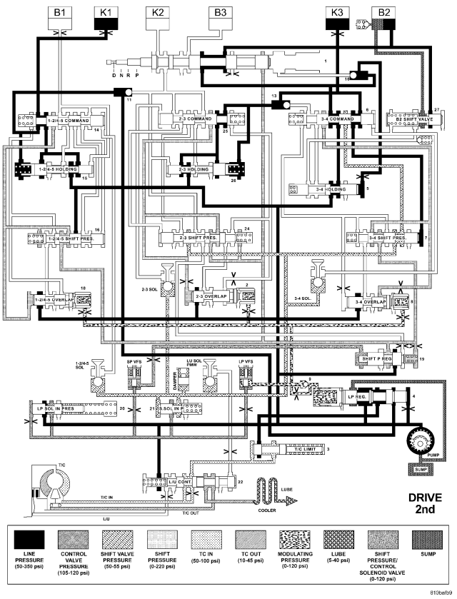
| HYDRAULIC FLOW IN DRIVE - SECOND GEAR |
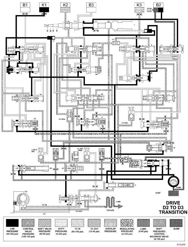
| HYDRAULIC FLOW IN DRIVE - SECOND TO THIRD GEAR TRANSITION |
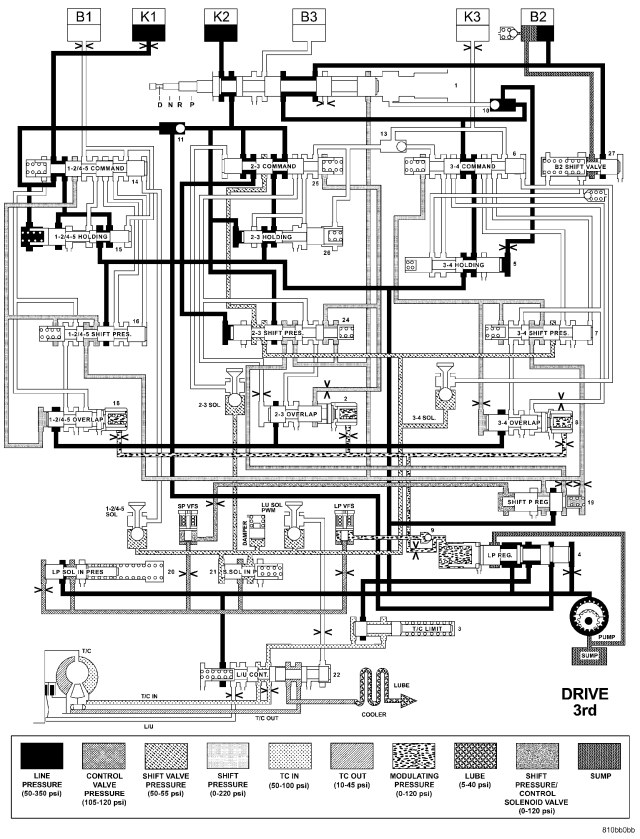
| HYDRAULIC FLOW IN DRIVE - THIRD GEAR |
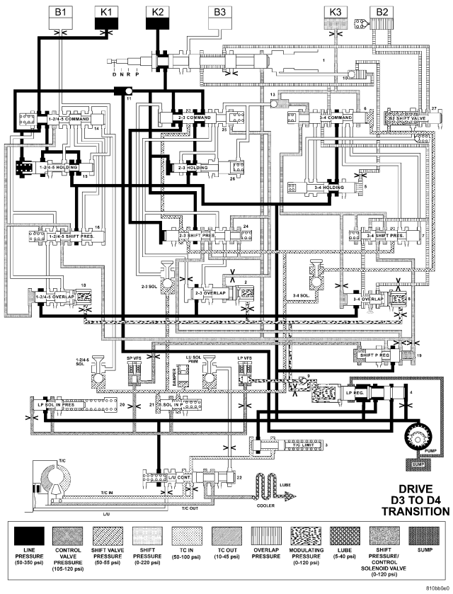
| HYDRAULIC FLOW IN DRIVE - THIRD TO FOURTH GEAR TRANSITION |
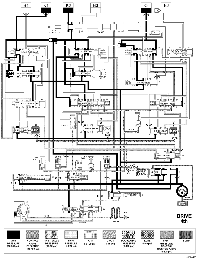
| HYDRAULIC FLOW IN DRIVE - FOURTH GEAR |
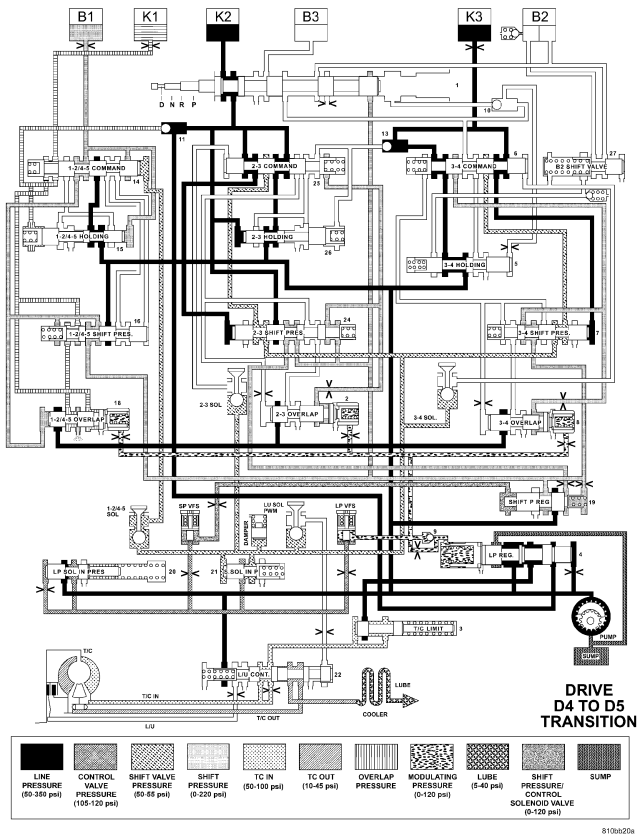
| HYDRAULIC FLOW IN DRIVE - FOURTH TO FIFTH GEAR TRANSITION |
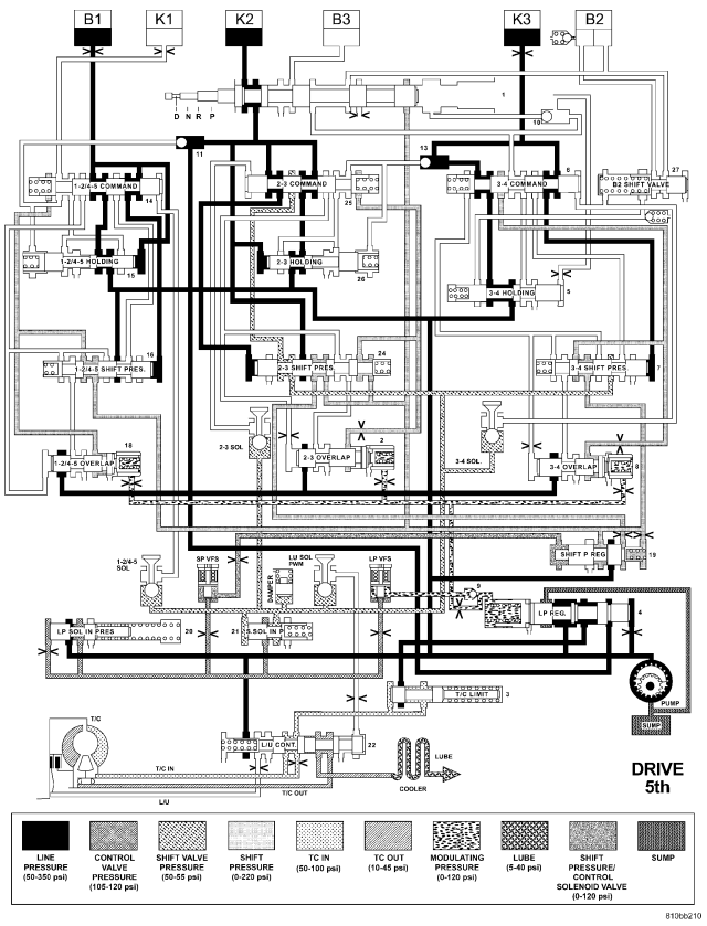
| HYDRAULIC FLOW IN DRIVE - FIFTH GEAR |
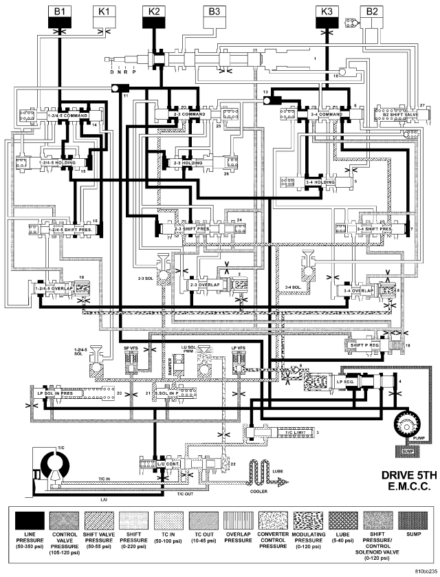
| HYDRAULIC FLOW IN DRIVE - FIFTH GEAR - EMCC |
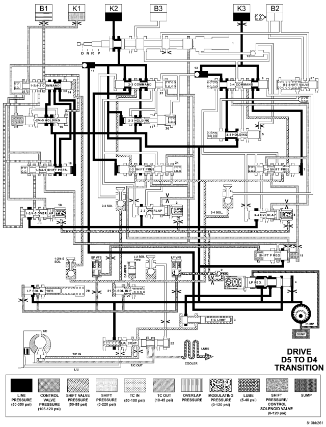
| HYDRAULIC FLOW IN DRIVE - FIFTH TO FOURTH GEAR TRANSITION |
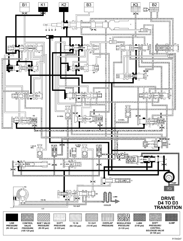
| HYDRAULIC FLOW IN DRIVE - FOURTH TO THIRD GEAR TRANSITION |
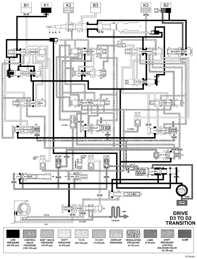
| HYDRAULIC FLOW IN DRIVE - THIRD TO SECOND GEAR TRANSITION |
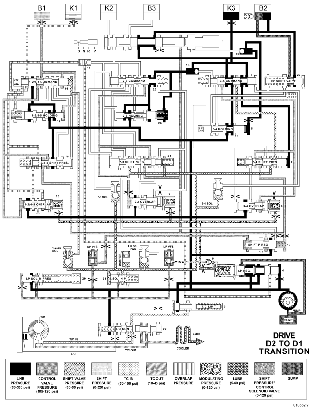
| HYDRAULIC FLOW IN DRIVE - SECOND TO FIRST GEAR TRANSITION |
SPECIFICATIONS
| 1ST |
3.59:1 |
| 2ND |
2.19:1 |
| 3RD |
1.41:1 |
| 4TH |
1.00:1 |
| 5TH |
0.83:1 |
| REVERSE |
3.16:1 |
| REVERSE (In 4WD Low Range) |
1.93:1 |
COMPONENT |
METRIC (mm) |
INCH (in.) |
||
| Geartrain End-play |
0.3-0.5 |
0.012-0.020 |
||
| Geartrain End-play Shim |
0.2, 0.3, 0.4, and 0.5 |
0.008, 0.012, 0.016, 0.020 |
||
| Rear Planetary Gear Set End-play |
0.15-0.6 |
0.006-0.024 |
||
| Rear Planetary Gear Set Snap-rings |
3.0, 3.4, and 3.7 |
0.118, 0.134, 0.146 |
||
| B1 Clutch Clearance - Double Sided Friction Discs |
2 Disc |
2.3-2.7 |
0.091-0.106 |
|
| 3 Disc |
2.7-3.1 |
0.106-0.122 |
||
| 4 Disc |
3.0-3.4 |
0.118-0.134 |
||
| B1 Clutch Clearance - Single Sided Friction Discs |
4 Disc |
2.2-2.6 |
0.087-0.102 |
|
| 6 Disc |
2.4-2.8 |
0.095-0.110 |
||
| 8 Disc |
2.6-3.0 |
0.102-0.118 |
||
| B1 Clutch Snap-rings |
2.6, 2.9, 3.2, 3.5, 3.8, and 4.1 |
0.102, 0.114, 0.126, 0.138, 0.150, 0.162 |
||
| B2 Clutch Clearance |
4 Disc |
1.9-2.3 |
0.075-0.091 |
|
| 5 Disc |
2.0-2.4 |
0.079-0.095 |
||
| B2 Clutch Snap-rings |
2.9, 3.2, 3.5, 3.8, and 4.1 |
0.114, 0.126, 0.138, 0.150, 0.162 |
||
| B3 Clutch Clearance |
1.0-1.4 |
0.039-0.055 |
||
| B3 Clutch Snap-rings |
3.2, 3.5, 3.8, 4.1, 4.4, and 4.7 |
0.126, 0.138, 0.150, 0.162, 0.173, 0.185 |
||
| K1 Clutch Clearance - Double Sided Friction Discs |
3 Disc |
2.7-3.1 |
0.106-0.122 |
|
| 4 Disc |
3.0-3.4 |
0.118-0.134 |
||
| 5 Disc |
3.3-3.7 |
0.130-0.146 |
||
| 6 Disc |
3.6-4.0 |
0.142-0.158 |
||
| K1 Clutch Clearance - Single Sided Friction Discs |
6 Disc |
2.4-2.8 |
0.095-0.110 |
|
| 8 Disc |
2.6-3.0 |
0.102-0.118 |
||
| 10 Disc |
2.8-3.2 |
0.110-0.126 |
||
| 12 Disc |
2.9-3.3 |
0.114-0.130 |
||
| K1 Clutch Snap-rings |
2.6, 2.9, 3.2, 3.5, 3.8, and 4.1 |
0.102, 0.114, 0.126, 0.138, 0.150, 0.162 |
||
| K2 Clutch Clearance |
3 Disc |
2.3-2.7 |
0.091-0.106 |
|
| 4 Disc |
2.4-2.8 |
0.095-0.110 |
||
| 5 Disc |
2.5-2.9 |
0.099-0.114 |
||
| 6 Disc |
2.7-3.1 |
0.106-0.122 |
||
| K2 Clutch Snap-rings |
2.3, 2.6, 2.9, 3.2, 3.5, and 3.8 |
0.091, 0.102, 0.114, 0.126, 0.138, 0.150 |
||
| K3 Clutch Clearance - Double Sided Friction Discs |
3 Disc |
2.3-2.7 |
0.091-0.106 |
|
| 4 Disc |
2.4-2.8 |
0.095-0.110 |
||
| 5 Disc |
2.5-2.9 |
0.099-0.114 |
||
| K3 Clutch Clearance - Single Sided Friction Discs |
6 Disc |
2.3-2.7 |
0.091-0.106 |
|
| 8 Disc |
2.4-2.8 |
0.095-0.110 |
||
| 10 Disc |
2.5-2.9 |
0.099-0.114 |
||
| K3 Clutch Snap-rings |
2.0, 2.3, 2.6, 2.9, 3.2, and 3.5 |
0.079, 0.091, 0.102, 0.114, 0.126, 0.138 |
||
DESCRIPTION |
N·m |
Ft. Lbs. |
In. Lbs. |
| Bolt, B2 Clutch Carrier |
16 |
- |
141 |
| Bolt, B1 Carrier to Converter Housing |
10 |
- |
89 |
| Bolt, Oil Pump |
20 |
- |
177 |
| Nut, Propeller Flange |
200 |
148 |
- |
| Nut, 4X4 Adapter Shaft |
200 |
147.5 |
- |
| Bolt, Electrohydraulic Unit |
8 |
- |
71 |
| Bolt, Transmission Housing to Converter Housing |
20 |
- |
177 |
| Bolts, 4X4 Adapter Housing |
20 |
- |
177 |
| Bolts, Oil Pan |
8 |
- |
71 |
| Screws, Valve Body/Housing Side Cover |
4 |
- |
35 |
| Bolt, Shift Plate |
8 |
- |
71 |
| Bolt, Solenoid Leaf Spring |
8 |
- |
71 |
| Nut, Shifter Mechanism to Floor Pan |
12 |
- |
105 |
| Bolt, Adapter Plug |
2.5 |
- |
22 |
| Bolt, Transmission to Engine |
39 |
29 |
- |
| Bolt, Crossmember to Frame |
68 |
50 |
- |
| Bolt, Rear Support to Transmission |
47 |
39 |
- |
| Bolt, Clevis Bracket to Crossmember |
47 |
39 |
- |
| Bolt, Clevis Bracket to Rear Support |
68 |
50 |
- |
| Bolt, Torque Converter |
42 |
31 |
- |
SPECIAL TOOLS - AUTOMATIC TRANSMISSION - NAG1
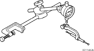
| Dial Indicator - C-3339 |
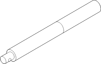
| Handle, Universal - C-4171 |
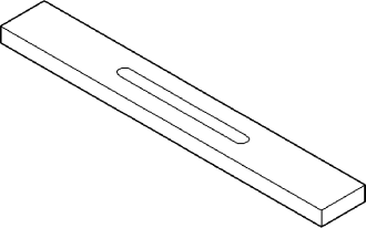
| Bar, Gauge - 6311 |
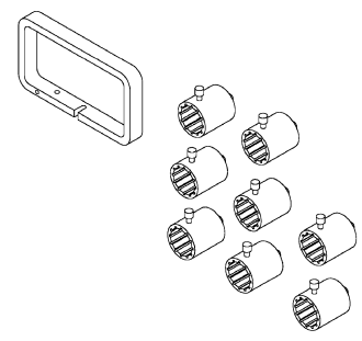
| End Play Set - 8266 |
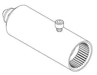
| Adapter, Geartrain End-play - 8266-18 |
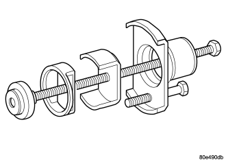
| Compressor, Multi-use Spring - 8900 |
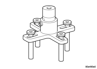
| Tool, Pressing - 8901 |
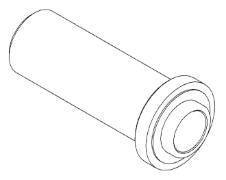
| Installer, Seal - 8902A |
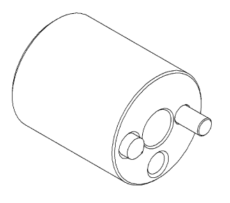
| Tool, Staking - 9078 |
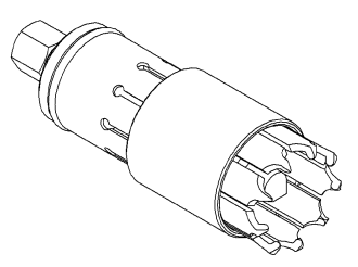
| Remover, Bearing - 9082 |
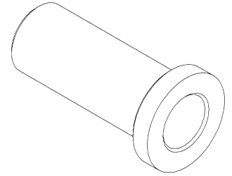
| Installer, Bearing - 9287 |
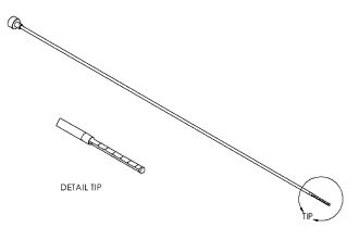
| Dipstick - 9336 |