DESCRIPTION
MANUAL SINGLE ZONE
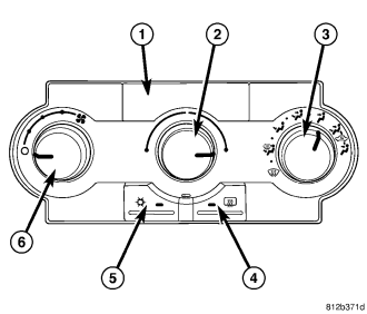
The A/C-heater control (1) for the manual temperature control (MTC) single zone heating-A/C system allows one temperature setting for the entire vehicle. All controls are identified by ISO graphic symbols.
The A/C-heater control and integral computer is located in the instrument panel and contains:
- a rotary control knob for temperature control of the discharged air (2).
- a rotary control knob for recirculation and mode control of the discharged air (3).
- a push button rear window defogger on/off control (4). The defogger button contains an LED that illuminates when the rear window defogger system is in operation.
- a push button A/C on/off control (5). The Snowflake button contains an LED that illuminates when the A/C system is in operation.
- a rotary control knob for fan speed selection and turning the heating-A/C system off (6).
Prior to replacing an A/C-heater control, check for any diagnostic trouble codes (DTCs) related to the heating-A/C system and run the calibration procedure to verify that the concern is not a system issue (refer to 24 - HEATING & AIR CONDITIONING - DIAGNOSIS AND TESTING - HEATING AND A/C SYSTEMS and to 24 - HVAC Electrical Diagnostics for more information).
The A/C-heater control cannot be repaired and must be replaced if found inoperative or damaged.
MANUAL SINGLE ZONE WITH REAR HEAT AND A/C
The A/C-heater controls for the manual temperature control (MTC) single zone front and rear heating-A/C system allows both the front and third row seat passengers the ability to regulate air temperature as well as fan speed and provides a floor outlet near the right rear door and upper air outlets at the top of each interior quarter trim panel. All controls are identified by ISO graphic symbols.
Prior to replacing an A/C-heater control, check for any diagnostic trouble codes (DTCs) related to the heating-A/C system and run the calibration procedure to verify that the concern is not a system issue (refer to 24 - HEATING & AIR CONDITIONING - DIAGNOSIS AND TESTING - HEATING AND A/C SYSTEMS and to 24 - HVAC Electrical Diagnostics for more information).
The front and rear A/C-heater controls cannot be repaired and, if faulty or damaged, they must be replaced.
FRONT CONTROL PANEL
The front A/C-heater control and integral computer is located in the instrument panel and contains:
- a rotary control knob for temperature control of the discharged air (2).
- a rotary control knob for recirculation and mode control of the discharged air (3).
- a push button rear window defogger on/off control (4). The defogger button contains an LED that illuminates when the rear window defogger system is in operation.
- a push button A/C on/off control (5). The Snowflake button contains an LED that illuminates when the A/C system is in operation.
- a rotary control knob for fan speed selection and turning the front heating-A/C system off (6).
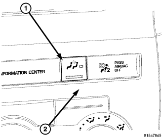
Primary on/off control for the rear blower motor is provided by a switch (1) located in the accessory swich bezel (2) above the front A/C-heater control.
REAR CONTROL PANEL
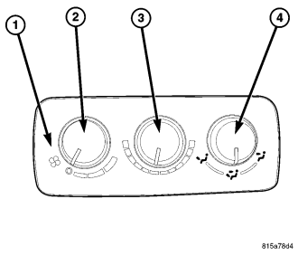
The rear A/C-heater control (1) is located on the right quarter interior trim panel and allows intermediate seat passengers to adjust rear air distribution, temperature and blower motor speed when the rear on/off control switch in the accessory switch bezel is set to the On position (refer to 24 - HEATING & AIR CONDITIONING/CONTROLS - REAR/CONTROL-A/C HEATER - DESCRIPTION).
The rear A/C-heater control contains:
- a rotary control knob for fan speed selection and turning the rear heating-A/C system off (2).
- a rotary control knob for temperature control of the rear discharged air (3).
- a rotary control knob for mode control of the rear discharged air (4).
The A/C-heater control cannot be repaired and must be replaced if found inoperative or damaged.
AUTOMATIC DUAL ZONE
The A/C-heater control (1) for the automatic temperature control (ATC) dual zone heating-A/C system allows both the driver and the front seat passenger the ability to individually regulate air temperature for their side of the vehicle. All controls are identified by ISO graphic symbols.
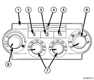
The ATC A/C-heater control and integral computer is located in the instrument panel and contains:
- a push button A/C on/off control (2). The Snowflake button contains an LED that illuminates when the A/C system is in operation.
- a push button rear window defogger on/off control (3). The defogger button contains an LED that illuminates when the rear window defogger system is in operation.
- an infrared sensor (4) that detects thermal radiation emitted by the front seat occupants and their surroundings
- a push button air recirculation control (5). The Recirculation button contains an LED that illuminates when the recirculation function is manually activated.
- a rotary control knob for mode control of the discharged air (6).
- two rotary control knobs for individual driver and front seat passenger temperature control of the discharged air (7).
- a rotary control knob for manual and automatic fan speed selection and turning the heating-A/C system off (8).
- Auto mode provides variable air recirculation under high temperature and humidity conditions. Because recirculation is generally accompanied by increased fan noise, the proportion of recirculated to outside air gradually approaches full recirculation over a broad temperature range.
The A/C-heater control for the ATC dual zone heating-A/C system is diagnosed using a scan tool. Prior to replacing an A/C-heater control, check for any diagnostic trouble codes (DTCs) related to the heating-A/C system and run the calibration procedure to verify that the concern is not a system issue (refer to 24 - HEATING & AIR CONDITIONING - DIAGNOSIS AND TESTING - HEATING AND A/C SYSTEMS and to 24 - HVAC Electrical Diagnostics for more information).
The A/C-heater control cannot be repaired and must be replaced if found inoperative or damaged.
The ATC A/C-heater control utilizes integrated circuitry and information carried on the controller area network (CAN) B bus to monitor many sensors and switch inputs throughout the vehicle. In response to those inputs, the internal circuitry and programming of the ATC A/C-heater control allows it to control electronic functions and features of the ATC heating-A/C system.
Some of the inputs received by the A/C-heater control of the ATC heating-A/C system on the CAN B bus are as follows:
- Controlhead backlight dimming
- Refrigerant Pressure
- A/C Clutch Engage
- Vehicle Identification Number
- Vehicle Odometer
- Engine Coolant Temperature
- Ambient Air Temperature
- System Voltage
- Vehicle Speed
- Engine Speed
Some of the messages broadcasted by the A/C-heater control of the ATC heating-A/C system on the CAN B bus are as follows:
- A/C Request
- A/C Select
- EBL Status