HOUSING-HVAC
DESCRIPTION
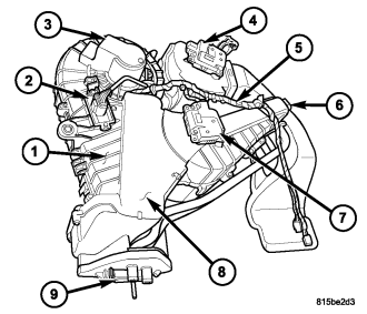
Models equipped with the rear heating-A/C system are equipped with a common rear heater and A/C housing (1) that combines A/C and heating capabilities into a single unit mounted within the rear passenger compartment. The rear heating-A/C system is a blend-air type system. A blend-air door controls the amount of conditioned air that is allowed to flow through, or around, the heater core (6). The rear A/C system is designed for the use of a non-CFC, R-134a refrigerant and uses an A/C expansion valve (9) and A/C evaporator (8) to cool and dehumidify the incoming air prior to blending it with the heated air. A temperature control determines the discharge air temperature by operating the blend door actuator (7), which moves the blend-air door. This allows an almost immediate control of the output air temperature of the rear system. The mode control operates the mode door actuator (4) that positions the mode-air door to direct the flow of the conditioned air out the upper or lower air outlets, depending on the position selected. Both electric door actuators are connected to the vehicle electrical system by the HVAC wire harness (5). The rear blower motor (3) controls the velocity of air flowing through the rear HVAC housing by spinning the blower wheel within the rear housing at the selected speed by use of the rear blower motor resistor (2).
The rear HVAC housing must be removed from the vehicle for service of the mode door actuator, blend door actuator, blower motor and blower motor resistor and, it must be disassembled for service of the A/C evaporator, heater core, mode-air door and blend-air door.
REMOVAL
WARNING: Refer to the applicable warnings and cautions for this system before performing the following operation (refer to 24 - HEATING & AIR CONDITIONING/PLUMBING - FRONT - WARNING) and (refer to 24 - HEATING & AIR CONDITIONING/PLUMBING - FRONT - CAUTION). Failure to follow the warnings and cautions could result in possible personal injury or death.
NOTE: The rear HVAC housing must be removed from the vehicle for service of the mode door actuator, blend door actuator, blower motor and blower motor resistor and, it must be disassembled for service of the A/C evaporator, heater core, mode-air door and blend-air door.
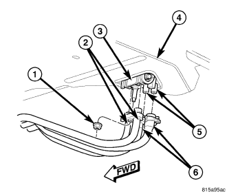
NOTE: Illustration shown with rear body cradle removed for clarity.
1. Disconnect and isolate the negative battery cable.
2. Recover the refrigerant from the refrigerant system (refer to 24 - HEATING & AIR CONDITIONING/PLUMBING - FRONT - STANDARD PROCEDURE - REFRIGERANT SYSTEM RECOVERY).
3. Drain the engine cooling system (refer to 7 - COOLING - STANDARD PROCEDURE - COOLING SYSTEM DRAIN).
4. Raise and support the vehicle.
5. Remove the nut (1) that secures the underbody refrigerant lines (2) to the rear A/C expansion valve (3) which extends through the rear floor panel (4) behind the right rear wheel housing.
6. Disconnect the rear underbody refrigerant lines from the rear A/C expansion valve and remove and discard the O-ring seals.
7. Install plugs in, or tape over the opened underbody refrigerant line fittings and rear expansion valve ports.
8. Disconnect the rear heater hoses (6) from the rear heater core tubes (5) which extends through the rear floor panel.
9. Lower the vehicle.
10. Remove right rear quarter panel trim (refer to 23 - BODY/INTERIOR/TRIM-QUARTER PANEL - REMOVAL).
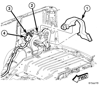
11. Disengage the retainer that secures the distribution duct (1) to the rear of the HVAC housing (2) and remove the duct
12. Disconnect the rear HVAC wire harness connector (3) from the body wire harness connector (4).
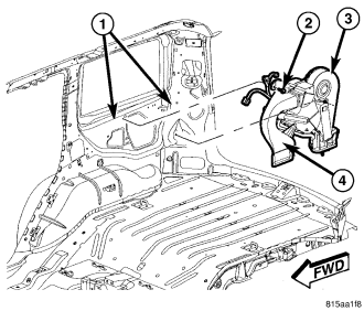
13. Remove the one nut and one bolt (2) that secure the rear HVAC housing (3) to the rear interior quarter panel (1).
14. Remove the rear HVAC housing from the vehicle and if required, remove the distribution duct (4) from the front of the HVAC housing.
DISASSEMBLY
NOTE: The rear HVAC housing must be removed from the vehicle for service of the mode door actuator, blend door actuator, blower motor and blower motor resistor and, it must be disassembled for service of the A/C evaporator, heater core, mode-air door and blend-air door.
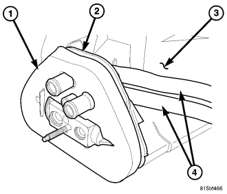
1. Remove the rear HVAC housing and place it on a workbench (refer to 24 - HEATING & AIR CONDITIONING/DISTRIBUTION - REAR/HOUSING-HVAC - REMOVAL).
2. Carefully remove the foam seal (1) from the flange (2) located at the bottom of the rear HVAC housing (3). If the seal is deformed or damaged, it must be replaced.
3. Partially bend the inner half of the flange downward and remove the heater core tubes (4) from the flange.
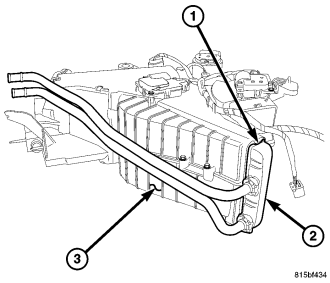
4. Release the two tabs (1) that secure the rear heater core (2) in the rear HVAC housing (3).
5. Carefully pull the rear heater core out of the end of the rear HVAC housing. If the foam seals on the heater core are deformed or damaged, they must be replaced.
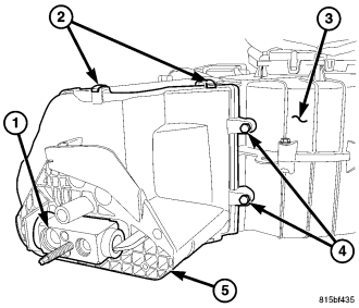
6. If required, remove the rear A/C expansion valve (1) from the rear A/C evaporator (refer to 24 - HEATING & AIR CONDITIONING/PLUMBING - REAR/VALVE-A/C EXPANSION - REMOVAL).
7. Remove the four clips (2) and four screws (4) that secure the flange (5) to the bottom of the rear HVAC housing (3) and remove the flange.
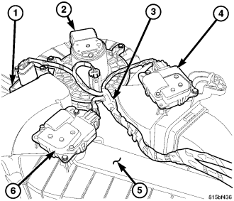
8. Disconnect the rear HVAC wire harness (3) from the rear blower motor resistor (1), rear blower motor (2), rear mode door actuator (4) and the rear blend door actuator (6) and remove the wire harness from the rear HVAC housing (5).
9. Remove the rear blower motor resistor (refer to 24 - HEATING & AIR CONDITIONING/CONTROLS - REAR/RESISTOR-BLOWER MOTOR - REMOVAL).
10. Remove the rear blower motor (refer to 24 - HEATING & AIR CONDITIONING/DISTRIBUTION - REAR/MOTOR-BLOWER - REMOVAL).
11. Remove the rear mode door actuator and rear blend door actuator (refer to 24 - HEATING & AIR CONDITIONING/CONTROLS - REAR/ACTUATOR-MODE DOOR - REMOVAL) and (refer to 24 - HEATING & AIR CONDITIONING/CONTROLS - REAR/ACTUATOR-BLEND DOOR - REMOVAL) .
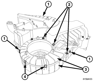
12. Remove the 15 screws (2) and three metal clips (4) that secure the two halves of the rear HVAC housing (3) together.
13. Release the three plastic retaining tabs (1) that secure the two halves of the rear HVAC housing together and separate the housing halves.
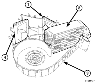
14. Carefully lift the rear A/C evaporator (2) out of the inboard half of the rear HVAC housing (3).
15. Remove the mode-air door (4) and blend-air door (1) from the inboard half of the rear HVAC housing. If the foam seal on any air-door is deformed or damaged, the air door must be replaced.
ASSEMBLY
CAUTION: Be certain to adjust the refrigerant oil level when servicing the A/C refrigerant system (refer to 24 - HEATING & AIR CONDITIONING/PLUMBING - FRONT/REFRIGERANT OIL - STANDARD PROCEDURE - REFRIGERANT OIL LEVEL). Failure to properly adjust the refrigerant oil level will prevent the A/C system from operating as designed and can cause serious A/C compressor damage.
NOTE: When replacing multiple A/C system components, refer to the Refrigerant Oil Capacities chart to determine how much oil should be added to the refrigerant system (refer to 24 - HEATING & AIR CONDITIONING/PLUMBING - FRONT/REFRIGERANT OIL - STANDARD PROCEDURE - REFRIGERANT OIL LEVEL).
NOTE: If the rear A/C evaporator is being replaced, add 30 milliliters (1 fluid ounce) of refrigerant oil to the refrigerant system. Use only refrigerant oil of the type recommended for the A/C compressor in the vehicle.
1. Install the blend-air door (1) and the mode-air door (4) onto the pivots located in the inboard half of the rear HVAC housing (3).
2. Install the rear A/C evaporator (2) into the inboard half of the rear HVAC housing.
3. Align the pivot shafts of the blend-air door and the mode-air door to the pivot holes located in the outboard half of the rear HVAC housing and install the two halves of the rear housing (3) together. Make sure the three plastic retaining tabs (1) are fully engaged.
4. Install the 15 screws (2) and three metal clips (4) that secure the two halves of the rear HVAC housing together. Tighten the screws to 2 N·m (17 in. lbs.).
5. Install the rear blend door actuator (6) and the rear mode door actuator (4) to the rear HVAC housing (5) (refer to 24 - HEATING & AIR CONDITIONING/CONTROLS - REAR/ACTUATOR-BLEND DOOR - INSTALLATION) and (refer to 24 - HEATING & AIR CONDITIONING/CONTROLS - REAR/ACTUATOR-MODE DOOR - INSTALLATION).
6. Install the rear blower motor (2) (refer to 24 - HEATING & AIR CONDITIONING/DISTRIBUTION - REAR/MOTOR-BLOWER - INSTALLATION).
7. Install the rear blower motor resistor (1) (refer to 24 - HEATING & AIR CONDITIONING/CONTROLS - REAR/RESISTOR-BLOWER MOTOR - INSTALLATION).
8. Install the rear HVAC wire harness (3) onto the rear HVAC housing and connect it to the rear blower motor resistor, rear blower motor, rear blend door actuator and the rear mode door actuator. Make sure the harness is routed through all wiring retainers.
9. Position the flange (5) onto the bottom of the rear HVAC housing (3). Make sure that the evaporator drain is clean and unrestricted.
10. Install the four screws (4) and four clips (2) that secure the flange to the bottom of the rear HVAC housing. Tighten the screws to 2 N·m (17 in. lbs.).
11. If removed, install the rear A/C expansion valve (1) onto the rear A/C evaporator (refer to 24 - HEATING & AIR CONDITIONING/PLUMBING - REAR/VALVE-A/C EXPANSION - INSTALLATION).
12. Install the rear heater core (2) into the end of the rear HVAC housing (3). Make sure that the foam seals are properly installed and that the two retaining tabs (1) are fully engaged.
13. Partially bend the inner half of the flange (2) located at the bottom of the rear HVAC housing (3) downward and install the heater core tubes (4) into the flange.
14. Install the foam seal (1) onto the flange. If the seal is deformed or damaged, it must be replaced.
15. Install the rear HVAC housing (refer to 24 - HEATING & AIR CONDITIONING/DISTRIBUTION - REAR/HOUSING-HVAC - INSTALLATION).
16. If the rear A/C evaporator is being replaced, add 30 milliliters (1 fluid ounce) of refrigerant oil to the refrigerant system. When replacing multiple A/C system components, refer to the Refrigerant Oil Capacities chart to determine how much oil should be added to the refrigerant system (refer to 24 - HEATING & AIR CONDITIONING/PLUMBING - FRONT/REFRIGERANT OIL - STANDARD PROCEDURE - REFRIGERANT OIL LEVEL). Use only refrigerant oil of the type recommended for the A/C compressor in the vehicle.
INSTALLATION
1. If removed, install the distribution duct (4) onto the front of the rear HVAC housing (3).
2. Position the rear HVAC housing into the vehicle.
3. Install the one nut and one bolt (2) that secure the rear HVAC housing to the rear interior quarter panel (1). Tighten the fasteners to 3 N·m (27 in. lbs.).
4. Connect the rear HVAC wire harness connector (3) to the body wire harness connector (4).
5. Install the distribution duct (1) onto the rear of the HVAC housing (2) and engage the retainer to the housing.
6. Install the right rear quarter panel trim (refer to 23 - BODY/INTERIOR/TRIM-QUARTER PANEL - INSTALLATION).
NOTE: Illustration shown with rear body cradle removed for clarity.
7. Raise and support the vehicle.
8. Connect the rear heater hoses (6) to the rear heater core tubes (5) which extend through the rear floor panel (4) behind the right rear wheel housing and install the heater hose clamps securely.
9. Remove the tape or plugs from rear underbody refrigerant line fittings and rear expansion valve ports.
10. Lubricate new rubber O-ring seals with clean refrigerant oil and install them onto the rear underbody refrigerant line fittings. Use only the specified O-rings as they are made of a special material for the R-134a refrigerant system. Use only refrigerant oil of the type recommended for the A/C compressor in the vehicle.
11. Connect the underbody refrigerant lines to the rear A/C expansion valve (3).
12. Install the nut (1) that secures the underbody refrigerant lines to the to the rear A/C expansion valve. Tighten the nut to 23 N·m (17 ft. lbs.).
13. Lower the vehicle.
14. Reconnect the negative battery cable.
15. If the heater core is being replaced, flush the cooling system (Refer to 7 - COOLING - STANDARD PROCEDURE - COOLING SYSTEM CLEANING/REVERSE FLUSHING).
16. Fill the engine cooling system (refer to 7 - COOLING - STANDARD PROCEDURE - COOLING SYSTEM FILL).
17. Evacuate the refrigerant system (refer to 24 - HEATING & AIR CONDITIONING/PLUMBING - FRONT - STANDARD PROCEDURE - REFRIGERANT SYSTEM EVACUATE).
18. Charge the refrigerant system (refer to 24 - HEATING & AIR CONDITIONING/PLUMBING - FRONT - STANDARD PROCEDURE - REFRIGERANT SYSTEM CHARGE).
19. Initiate the Actuator Calibration function using a scan tool (refer to HVAC System Test, found in 24 - HVAC - Electrical Diagnostics).