*NO CRANK CONDITION
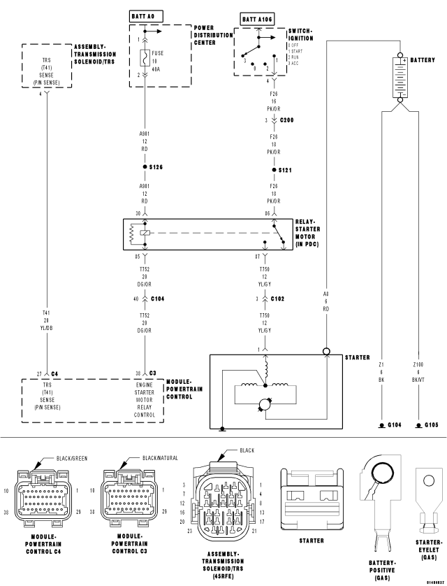
For a complete wiring diagram Refer to Section 8W.
| Possible Causes |
| MECHANICAL CONDITION |
| BATTERY CIRCUIT RESISTANCE TOO HIGH |
| (F26) FUSED IGNITION SWITCH OUTPUT CIRCUIT |
| (A901) FUSED B+ CIRCUIT OPEN |
| (T752) STARTER RELAY CONTROL CIRCUIT OPEN |
| (T750) STARTER RELAY OUTPUT CIRCUIT OPEN |
| TRANSMISSION RANGE SENSOR |
| STARTER RELAY |
| STARTER |
Diagnostic Test
1. MECHANICAL CONDITIONNOTE: Verify the battery is fully charged and capable of passing a load test before continuing.
WARNING: Make sure the battery is disconnected, then wait two minutes before proceeding. Failure to do so may result in personal injury or possible death.
Turn the engine over by hand to make sure the engine is not seized.
Is the engine able to turn over?
Yes
- Go To 2
No
- Repair the mechanical condition preventing the starter motor from cranking.
- Perform the POWERTRAIN VERIFICATION TEST. (Refer to 9 - ENGINE - STANDARD PROCEDURE)
2. TRANSMISSION RANGE SENSOR
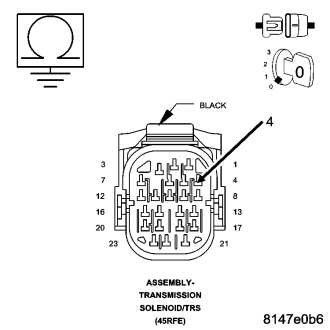
Turn the ignition off.
Disconnect the TRS harness connectors.
Move the Gear selector through all gear positions, from Park to 1st and back.
While moving the gear selector through each gear, measure the resistance between ground and the TRS (T41) Sense (P/N Sense) circuit at the TRS connector.
NOTE: The circuit is grounded in Park and Neutral and open in the other positions.
Did the resistance change from above 100 kohms (open) to below 10.0 ohms (grounded) ?
Yes
- Go To 3
No
- Replace the Transmission Range Sensor.
- Perform the POWERTRAIN VERIFICATION TEST. (Refer to 9 - ENGINE - STANDARD PROCEDURE)
3. EXCESSIVE RESISTANCE IN THE BATTERY CIRCUIT
Turn the ignition off.
Check the Battery Cables for excessive resistance using the service information procedure.
Did either Battery Cable have a voltage drop greater than 0.2 of a volt?
Yes
- Repair the excessive resistance in the Battery circuit.
- Perform the POWERTRAIN VERIFICATION TEST. (Refer to 9 - ENGINE - STANDARD PROCEDURE)
No
- Go To 4
4. STARTER RELAY
Turn ignition off.
Remove the Starter Relay from IPM.
CAUTION: The Parking Brake must be on and the Transmission must be in park for a vehicle equipped with an automatic transmission.
WARNING: When the engine is operating, do not stand in direct line with the fan. Do not put your hands near the pulleys, belts, or fan. Do not wear loose clothing. Failure to follow these instructions can result in personal injury or death.
Briefly connect a jumper wire between (A901) Fused B+ circuit and the (T750) Starter Relay Output circuit.
Did the Starter Motor crank the engine?
Yes
- Go To 5
No
- Go To 7
5. (F26) FUSED IGNITION SWITCH OUTPUT CIRCUIT
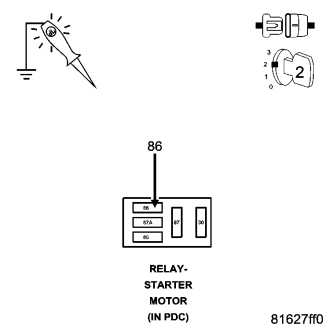
Ignition on, engine not running.
Using a 12-volt test light, probe the (F26) Fused Ignition Switch Output circuit in the Starter Relay connector.
While observing 12-volt test light, hold ignition key in the start position.
Does the test light illuminate brightly?
Yes
- Go To 6
No
- Repair the excessive resistance in the (F26) Fused Ignition Switch Output circuit. Inspect related fuses and repair as necessary.
- Perform the POWERTRAIN VERIFICATION TEST. (Refer to 9 - ENGINE - STANDARD PROCEDURE)
6. (T752) STARTER RELAY CONTROL CIRCUIT OPEN
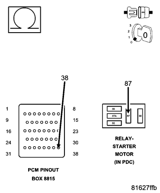
Turn the ignition off.
Remove the Starter Relay from the IPM.
Disconnect the C3 PCM harness connector.
Measure the resistance in the (T752) Starter Relay Control circuit from the Relay terminal to the appropriate terminal of special tool #8815.
Is the resistance below 5.0 ohms?
Yes
- Replace the Starter Motor Relay.
- Perform the POWERTRAIN VERIFICATION TEST. (Refer to 9 - ENGINE - STANDARD PROCEDURE)
No
- Repair the open in the (T752) Starter Relay Control circuit.
- Perform the POWERTRAIN VERIFICATION TEST. (Refer to 9 - ENGINE - STANDARD PROCEDURE)
7. (A901) FUSED B+ CIRCUIT
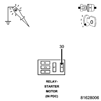
Turn the ignition off.
Using a 12-volt test light connected to ground, probe the (A901) Fused B+ circuit at the Starter Relay terminal.
Does the test light illuminate brightly?
Yes
- Go To 8
No
- Repair the excessive resistance or short to ground in the (A901) Fused B+ circuit. Inspect related fuses and repair as necessary.
- Perform the POWERTRAIN VERIFICATION TEST. (Refer to 9 - ENGINE - STANDARD PROCEDURE)
8. (T750) STARTER RELAY OUTPUT CIRCUIT OPEN
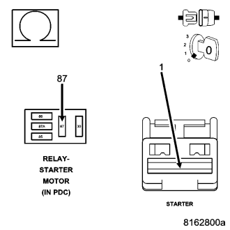
Disconnect the Starter Relay Output connector from the Starter Solenoid.
Measure the resistance of the (T750) Starter Relay Output circuit between the Relay and the Solenoid harness connector.
Is the resistance below 5.0 ohms?
Yes
- Go To 9
No
- Repair the open in the Starter Relay Output circuit.
- Perform the POWERTRAIN VERIFICATION TEST. (Refer to 9 - ENGINE - STANDARD PROCEDURE)
9. STARTER
If there are no other possible causes remaining, review repair.
Repair
- Replace the Starter.
- Perform the POWERTRAIN VERIFICATION TEST. (Refer to 9 - ENGINE - STANDARD PROCEDURE)