P050B-COLD START IGNITION TIMING PERFORMANCE (NON ETC)
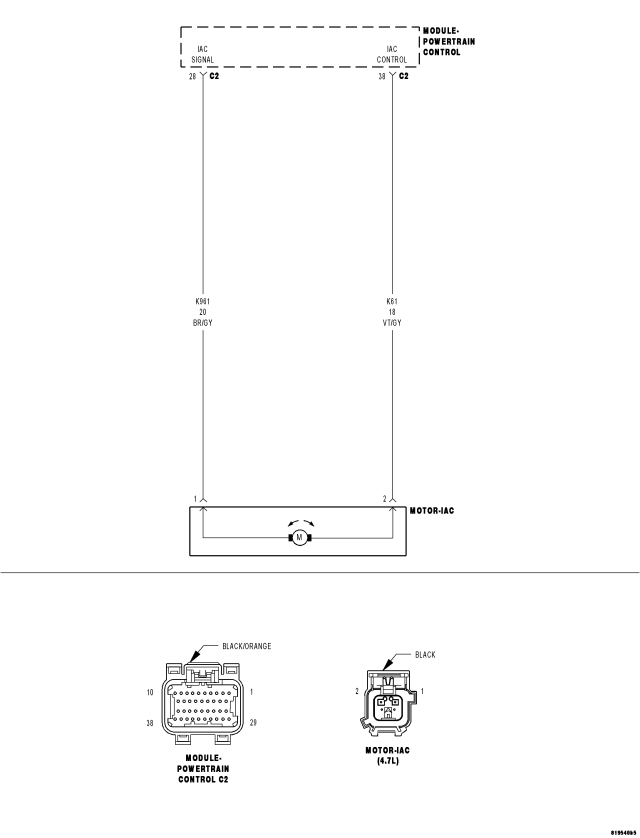
For a complete wiring diagram Refer to Section 8W.
Theory of Operation
Spark adjustment during a cold start is intended to provide quick response to idle speed variations. The spark adjust diagnostics monitors spark advance on a cold start over a period of time, then compares the average spark advance to a threshold.
- When Monitored:
Cold start condition. Ambient Air temperature between -7°C and 50 °C (19.4°F and 122°F). Engine Coolant temperature between -7°C and 50 °C (19.4°F and 122°F). The difference between the Ambient Air temp and ECT temp at Start is equal to or less than 10°C (50°F). Engine running at idle only.
- Set Condition:
Engine RPM is 50 RPM or more (depending on vehicle specifications), below idle speed for at least 3 seconds and the average spark advance is above the threshold, too much spark advance, for a specified time limit. Two trip fault. Three good trips to turn off the MIL.
| Possible Causes |
| RESTRICTED INTAKE AIR SYSTEM |
| LOW BATTERY VOLTAGE |
| FUEL CONTAMINATION |
| EXCESSIVE RESISTANCE IN THE (K61) IAC CONTROL CIRCUIT |
| EXCESSIVE RESISTANCE IN THE (K961) IAC SIGNAL CIRCUIT |
| IAC/THROTTLE BODY |
| PCM |
Always perform the Pre-Diagnostic Troubleshooting procedure before proceeding. (Refer to 9 - ENGINE - DIAGNOSIS AND TESTING).
Diagnostic Test
1. ACTIVE DTCIgnition on, engine not running.
NOTE: Low battery voltage can also cause excessive current draw, in very hot and very cold ambient temperatures. Make sure the battery can pass a load test before continuing.
Start the engine.
Allow the engine to reach normal operating temperature.
With a scan tool, select View DTCs.
NOTE: It may be necessary to drive the vehicle to meet the conditions to set this DTC, try to repeat the conditions in which the fault originally set by reviewing the Freeze Frame data.
Is the DTC Active or Pending at this time?
Yes
- Go To 2
No
- Refer to the INTERMITTENT CONDITION Diagnostic Procedure.
- Perform the POWERTRAIN VERIFICATION TEST. (Refer to 9 - ENGINE - STANDARD PROCEDURE)
2. THROTTLE PLATE INSPECTION
Turn the ignition off.
Remove the Air Cleaner Assembly from the Throttle Body.
Check for any broken components in the Throttle Body.
Check for any signs of a foreign material (ice, dirt, or excessive carbon build up) on the Throttle Plate or in the bore causing the Throttle Plate to stick.
Were any signs of foreign material or scoring of the throttle plate or bore found?
Yes
- Remove the debris if possible or replace the Throttle Body Assembly as necessary.
- Perform the POWERTRAIN VERIFICATION TEST. (Refer to 9 - ENGINE - STANDARD PROCEDURE)
No
- Go To 3
3. DIRTY AIR FILTER
Remove and inspect the Air Filter.
Is the Air Filter dirty?
Yes
- Replace the Air Filter.
- Perform the POWERTRAIN VERIFICATION TEST. (Refer to 9 - ENGINE - STANDARD PROCEDURE)
No
- Go To 4
4. CONTAMINATED FUEL
Inspect the Fuel for contamination. (Dirt, water, or other foreign material)
Is the fuel contaminated?
Yes
- Drain the Fuel from the fuel tank into an approved gas holding tank and add clean fuel. (Refer to 14 - FUEL SYSTEM/FUEL DELIVERY - STANDARD PROCEDURE)
No
- Go To 5
5. EXCESSIVE RESISTANCE IN THE (K961) IAC SIGNAL CIRCUIT
Turn the ignition off.
Disconnect the C2 harness connector.
CAUTION: Do not probe the PCM harness connectors. Probing the PCM harness connectors will damage the PCM terminals resulting in poor terminal to pin connection. Install Miller Special Tool #8815 along with the #8815-1 to perform the diagnosis.
Using a voltmeter perform a voltage drop test. Backprobe the (K961) IAC Signal circuit at the IAC harness connector and probe the appropriate terminal of the special tool #8815. Make sure the voltmeter leads are connected so a positive polarity is displayed on the voltmeter.
WARNING: When the engine is operating, do not stand in direct line with the fan. Do not put your hands near the pulleys, belts, or fan. Do not wear loose clothing. Failure to follow these instructions can result in personal injury or death.
Start the engine and allow it to reach normal operating temperature.
Monitor the voltmeter.
Is the voltage below 0.5 of a volt?
Yes
- Go To 6
No
- Repair the excessive resistance in the (K961) IAC Signal circuit.
- Perform the POWERTRAIN VERIFICATION TEST. (Refer to 9 - ENGINE - STANDARD PROCEDURE)
6. EXCESSIVE RESISTANCE IN THE (K61) IAC CONTROL CIRCUIT
Turn the ignition off.
Move the voltmeter leads to backprobe the (K61) IAC Control circuit at the IAC harness connector and to probe the appropriate terminal of the special tool #8815. Make sure the voltmeter leads are connected so a positive polarity is displayed on the voltmeter.
WARNING: When the engine is operating, do not stand in direct line with the fan. Do not put your hands near the pulleys, belts, or fan. Do not wear loose clothing. Failure to follow these instructions can result in personal injury or death.
Start the engine and allow it to reach normal operating temperature.
Monitor the voltmeter.
Is the voltage below 0.5 of a volt?
Yes
- Go To 7
No
- Repair the excessive resistance in the (K61) IAC Control circuit.
- Perform the POWERTRAIN VERIFICATION TEST. (Refer to 9 - ENGINE - STANDARD PROCEDURE)
7. IAC MOTOR
Turn the ignition off.
Disconnect the IAC Motor harness connector.
Remove special tool #8815 and #8815-1.
Connect the C2 PCM harness connector.
Remove the IAC Motor.
NOTE: Inspect the IAC air passages for restrictions and damage to the IAC valve and clean as necessary.
Measure the resistance across the IAC Motor pin terminals (component).
Is the resistance 9.7 +/- 1.0 ohms?
Yes
- Go To 8
No
- Replace the IAC Motor.
- Perform the POWERTRAIN VERIFICATION TEST. (Refer to 9 - ENGINE - STANDARD PROCEDURE)
8. PCM
NOTE: Before continuing, check the PCM harness connector terminals for corrosion, damage, or terminal push out. Repair as necessary.
Using the schematics as a guide, inspect the wire harness and connectors. Pay particular attention to all Power and Ground circuits.
Were there any problems found?
Yes
- Repair as necessary.
- Perform the POWERTRAIN VERIFICATION TEST. (Refer to 9 - ENGINE - STANDARD PROCEDURE)
No
- Replace and program the Powertrain Control Module per Service Information.
- Perform the POWERTRAIN VERIFICATION TEST. (Refer to 9 - ENGINE - STANDARD PROCEDURE)