P0524-ENGINE OIL PRESSURE TOO LOW
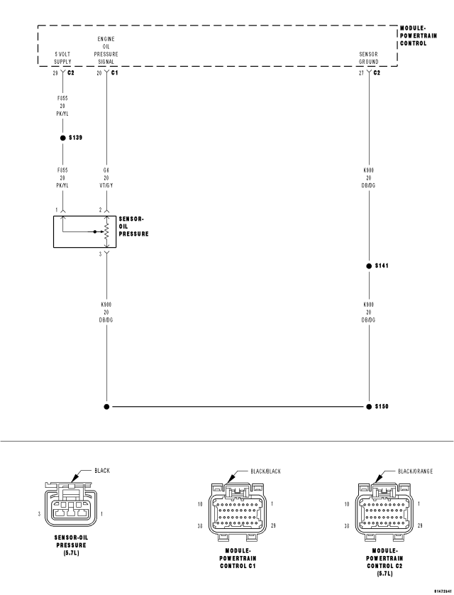
For a complete wiring diagram Refer to Section 8W.
- When Monitored:
Engine running.
- Set Condition:
The engine oil pressure never reaches the calibrated specification to allow the MDS activation. One trip fault.
| Possible Causes |
| ENGINE OIL/ENGINE MECHANICAL |
| (G6) ENGINE OIL PRESSURE SENSOR SIGNAL CIRCUIT SHORTED TO BATTERY VOLTAGE |
| RESISTANCE (G6) ENGINE OIL PRESSURE SENSOR SIGNAL CIRCUIT |
| (G6) ENGINE OIL PRESSURE SENSOR SIGNAL CIRCUIT SHORTED TO GROUND |
| RESISTANCE IN (F855) 5-VOLT SUPPLY CIRCUIT |
| (F855) 5-VOLT SUPPLY CIRCUIT SHORTED TO GROUND |
| RESISTANCE IN THE (K900) SENSOR RETURN CIRCUIT |
| ENGINE OIL PRESSURE SENSOR |
| PCM |
Always perform the Pre-Diagnostic Troubleshooting procedure before proceeding. (Refer to 9 - ENGINE - DIAGNOSIS AND TESTING).
Diagnostic Test
1. ACTIVE DTCNOTE: Make sure that the engine oil is at the proper level. Also, check the customers oil change history to make sure that the oil is being changed at the correct intervals and that the proper oil viscosity is being used.
Ignition on, engine not running.
With a scan tool, select View DTCs.
Is the DTC Active at this time?
Yes
- Go To 2
No
- Refer to the INTERMITTENT CONDITION Diagnostic Procedure.
- Perform the POWERTRAIN VERIFICATION TEST. (Refer to 9 - ENGINE - STANDARD PROCEDURE)
2. ENGINE OIL/ENGINE MECHANICAL
NOTE:
The following items must be considered before determining the cause of this DTC. Failure to do so may lead to misdiagnosis.
If any of the above conditions are found, repair as necessary.
Were any of the above conditions present?
Yes
- Repair as necessary.
- Perform the POWERTRAIN VERIFICATION TEST. (Refer to 9 - ENGINE - STANDARD PROCEDURE)
No
- Go To 3
3. ENGINE OIL PRESSURE SENSOR
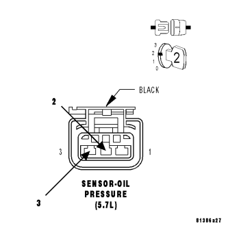
Turn the ignition off.
Connect the C2 PCM harness connector.
Ignition on, engine not running.
With a scan tool, monitor the Engine Oil Pressure Sensor voltage.
Connect a jumper wire between the (K900) Sensor Ground circuit and the (G6) Engine Oil Pressure Signal circuit.
NOTE: Engine Oil Pressure voltage should change from approximately 4.5 volts to less than 0.5 of a volt.
Is the voltage reading within the listed specification when the jumper wire is installed?
Yes
- Remove the Engine Oil Pressure sensor and ensure the oil passage/port is free from any blockage. If OK, replace the Engine Oil Pressure Sensor.
- Perform the POWERTRAIN VERIFICATION TEST. (Refer to 9 - ENGINE - STANDARD PROCEDURE)
No
- Go To 4
NOTE: Remove the jumper wire before continuing.
4. EXCESSIVE RESISTANCE IN THE (G6) ENGINE OIL PRESSURE SIGNAL CIRCUIT
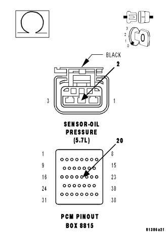
Turn the ignition off.
Disconnect the C1 PCM harness connector.
CAUTION: Do not probe the PCM harness connectors. Probing the PCM harness connectors will damage the PCM terminals resulting in poor terminal to pin connection. Install Miller Special Tool #8815 to perform diagnosis.
Measure the resistance of the (G6) Engine Oil Pressure Signal circuit from the Engine Oil Pressure Sensor harness connector to the appropriate terminal of special tool #8815.
Is the resistance below 5.0 ohms?
Yes
- Go To 5
No
- Repair the excessive resistance in the (G6) Engine Oil Pressure Signal circuit.
- Perform the POWERTRAIN VERIFICATION TEST. (Refer to 9 - ENGINE - STANDARD PROCEDURE)
5. (G6) ENGINE OIL PRESSURE SIGNAL CIRCUIT SHORTED TO GROUND
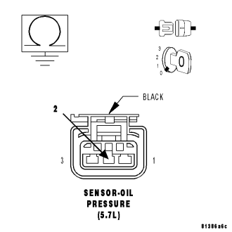
Measure the resistance between ground and the (G6) Engine Oil Pressure Signal circuit in the Engine Oil Pressure Sensor harness connector.
Is the resistance below 100 ohms?
Yes
- Repair the short to ground in the (G6) Engine Oil Pressure Signal circuit.
- Perform the POWERTRAIN VERIFICATION TEST. (Refer to 9 - ENGINE - STANDARD PROCEDURE)
No
- Go To 6
6. EXCESSIVE RESISTANCE IN THE (F855) 5–VOLT SUPPLY CIRCUIT
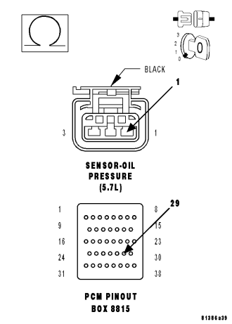
Measure the resistance of the (F855) 5-volt Supply circuit from the Engine Oil Pressure Sensor harness connector to the appropriate terminal of special tool #8815.
Is the resistance below 5.0 ohms?
Yes
- Go To 7
No
- Repair the excessive resistance in the (F855) 5-volt Supply circuit.
- Perform the POWERTRAIN VERIFICATION TEST. (Refer to 9 - ENGINE - STANDARD PROCEDURE)
7. (F855) 5-VOLT SUPPLY SHORTED TO GROUND
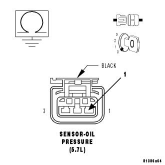
Measure the resistance between ground and the (F855) 5-volt Supply circuit in the Engine Oil Pressure Sensor harness connector.
Is the resistance below 100 ohms?
Yes
- Repair the short to ground in the (F855) 5-volt Supply circuit.
- Perform the POWERTRAIN VERIFICATION TEST. (Refer to 9 - ENGINE - STANDARD PROCEDURE)
No
- Go To 8
8. EXCESSIVE RESISTANCE IN THE (K900) SENSOR GROUND CIRCUIT
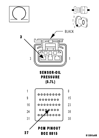
Measure the resistance of the (K900) Sensor Ground circuit from the Engine Oil Pressure Sensor harness connector to the appropriate terminal of special tool #8815.
Is the resistance below 5.0 ohms?
Yes
- Go To 9
No
- Repair the excessive resistance in the (K900) Sensor Ground circuit.
- Perform the POWERTRAIN VERIFICATION TEST. (Refer to 9 - ENGINE - STANDARD PROCEDURE)
9. PCM
NOTE: Before continuing, check the PCM harness connector terminals for corrosion, damage, or terminal push out. Repair as necessary.
Using the schematics as a guide, inspect the wire harness and connectors. Pay particular attention to all Power and Ground circuits.
Were there any problems found?
Yes
- Repair as necessary.
- Perform the POWERTRAIN VERIFICATION TEST. (Refer to 9 - ENGINE - STANDARD PROCEDURE)
No
- Replace and program the Powertrain Control Module per Service Information.
- Perform the POWERTRAIN VERIFICATION TEST. (Refer to 9 - ENGINE - STANDARD PROCEDURE)