P2504-CHARGING SYSTEM OUTPUT HIGH
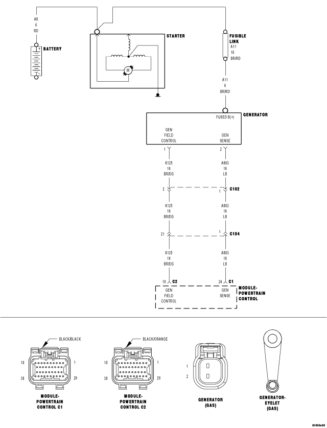
For a complete wiring diagram Refer to Section 8W.
- When Monitored:
The engine running. The engine speed greater than 1157 RPM.
- Set Condition:
The alternator B+ voltage sense circuit voltage reading exceeds the direct Battery B+ sense circuit. The Generator Output terminal is not connected to the Battery B+ post. One trip fault.
| Possible Causes |
| EXCESSIVE RESISTANCE IN THE (A209) BATTERY FEED CIRCUIT |
| PCM |
Always perform the Pre-Diagnostic Troubleshooting procedure before proceeding. (Refer to 9 - ENGINE - DIAGNOSIS AND TESTING).
Diagnostic Test
1. ACTIVE DTCNOTE: Inspect the vehicle for aftermarket accessories that may exceed the Generator System output.
NOTE: The battery must be fully charged.
NOTE: The Generator belt tension and condition must be checked before continuing.
Ignition on, engine not running.
With a scan tool, select View DTCs.
Read and record the related Freeze Frame data for P2504.
With a scan tool, erase DTCs.
Start the engine.
Allow the idle to stabilize.
With the scan tool, View DTCs.
Is the DTC Active at this time?
Yes
- Go To 2
No
- Refer to the INTERMITTENT CONDITION Diagnostic Procedure.
- Perform the POWERTRAIN VERIFICATION TEST. (Refer to 9 - ENGINE - STANDARD PROCEDURE)
2. (A11) BATTERY POSITIVE CIRCUIT VISUAL INSPECTION
Turn the ignition off.
Inspect the (A11) Battery Positive circuit at Generator Output post for corrosion and looseness.
Inspect the Battery + and – cables for corrosion and looseness.
Inspect the (A11) Battery Positive circuit at the Battery + post for corrosion and looseness.
Were any problems found?
Yes
- Repair and replace as necessary.
- Perform the POWERTRAIN VERIFICATION TEST. (Refer to 9 - ENGINE - STANDARD PROCEDURE)
No
- Go To 3
3. EXCESSIVE RESISTANCE IN THE (A209) BATTERY FEED CIRCUIT
CAUTION: Do not probe the PCM harness connectors. Probing the PCM harness connectors will damage the PCM terminals resulting in poor terminal to pin connection. Install Miller Special Tool #8815 and #8815-1 to perform diagnosis.
Disconnect the C1 PCM harness connector.
Inspect the Engine Control Direct Battery Feed Fuse in the PDC.
Perform a voltage drop test on the (A209) Battery Feed circuit from the appropriate terminal of special tool #8815–1 to the PDC Fuse Panel.
Using a voltmeter probe the appropriate terminal of special tool #8815-1 with the Negative lead of the voltmeter and back probe the (A209) Battery Feed circuit at the PDC Fuse Panel with the Positive lead of the voltmeter.
WARNING: When the engine is operating, do not stand in direct line with the fan. Do not put your hands near the pulleys, belts, or fan. Do not wear loose clothing. Failure to follow these instructions can result in personal injury or death.
Start the engine
Monitor the voltmeter.
Is the voltage above 0.4 of a volt?
Yes
- Repair the excessive resistance in the (A209) Battery Feed circuit between the PCM and IPM.
- Perform the POWERTRAIN VERIFICATION TEST. (Refer to 9 - ENGINE - STANDARD PROCEDURE)
No
- Go To 4
4. PCM
NOTE: Before continuing, check the PCM harness connector terminals for corrosion, damage, or terminal push out. Repair as necessary.
Turn the ignition off.
Using the schematics as a guide, inspect the wire harness and connectors. Pay particular attention to all Power and Ground circuits.
Were there any problems found?
Yes
- Repair as necessary.
- Perform the POWERTRAIN VERIFICATION TEST. (Refer to 9 - ENGINE - STANDARD PROCEDURE)
No
- Replace and program the Powertrain Control Module per Service Information.
- Perform the POWERTRAIN VERIFICATION TEST. (Refer to 9 - ENGINE - STANDARD PROCEDURE)