P3450-CYLINDER 7 DEACTIVATION CONTROL PERFORMANCE
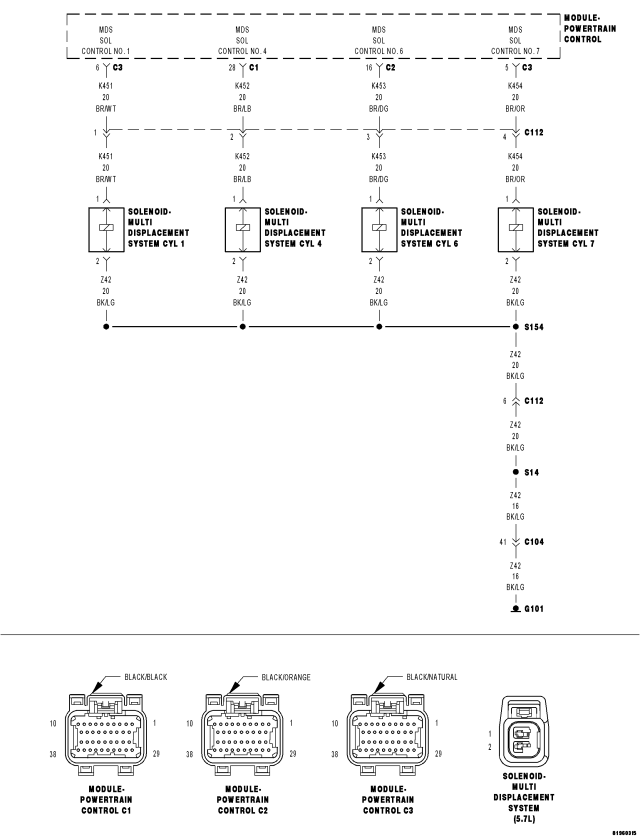
For a complete wiring diagram Refer to Section 8W.
Theory of Operation
When all criteria has been met, power is supplied to each MDS Solenoid when the engine is making a transition from 8 cylinder mode to 4 cylinder mode. By actuating the solenoid, oil pressure is raised to the pair of lifters that coincide with each particular solenoid. The oil pressure pushes in the locking pins that allows the lifter to collapse, decoupling the valves and camshaft.
- When Monitored:
Transition from 8 to 4 cylinder mode.
- Set Condition:
The MDS fails to engage for cylinder 7. One trip fault.
| Possible Causes |
| (K454) MDS SOLENOID NO.7 CONTROL SHORT TO GROUND |
| (K454) MDS SOLENOID NO.7 CONTROL OPEN |
| (Z42) GROUND CIRCUIT OPEN |
| INSUFFICIENT OIL PRESSURE ACTING ON THE LIFTER LOCKING PINS |
| OIL PASSAGES RESTRICTED |
| LIFTER |
| MDS SOLENOID |
| PCM |
Always perform the Pre-Diagnostic Troubleshooting procedure before proceeding. (Refer to 9 - ENGINE - DIAGNOSIS AND TESTING).
Diagnostic Test
1. ACTIVE DTCIgnition on, engine not running.
With a scan tool, select View DTCs.
Is the DTC Active at this time?
Yes
- Go To 2
No
- Refer to the INTERMITTENT CONDITION Diagnostic Procedure.
- Perform the POWERTRAIN VERIFICATION TEST. (Refer to 9 - ENGINE - STANDARD PROCEDURE)
2. CHECKING PCM CONTROL SIDE FOR THE MDS SOLENOID (C112)
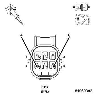
Turn the ignition off.
Disconnect the C112 harness connector.
Using a 12-volt test light, jumper from the (Z42) Ground Circuit and the (K454) MDS Solenoid No.7 Control Circuit in the C112 harness connector (PCM side).
Turn the ignition on.
With the scan tool, actuate the MDS Solenoid No.7.
Does the 12-volt test light flash on and off?
Yes
- Go To 3
No
- Go To 4
3. MDS SOLENOID RESISTANCE
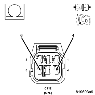
Turn the ignition off.
Measure the resistance between the (Z42) Ground Circuit and the (K454) MDS Solenoid No.7 Control Circuit in the C112 harness connector (MDS side).
NOTE: It is important to follow the below temp/resistance values to ensure an accurate reading.
| MDS SOLENOID RESISTANCE | |
| TEMPERATURE VALUE ± -7° C (20° F) | RESISTANCE (OHMS) ± .25 ohms |
| -18° C (0° F) | 8.8 ohms |
| 0° C (32° F) | 9.5 ohms |
| 20° C (68° F) | 10.3 ohms |
| 38° C (100° F) | 11 ohms |
| 66° C (150° F) | 12.2 ohms |
| 93° C (200° F) | 13.4 ohms |
| 121° C (250° F) | 14.4 ohms |
| 149° C (300° F) | 15.6 ohms |
Is the resistance within an acceptable range?
Yes
- Go To 7
No
- Visually and Physically inspect the wiring harness between the C112 connector and the MDS Solenoid connector. Repair as necessary. If OK, replace the MDS Solenoid in accordance with the Service Information.
4. (Z42) GROUND CIRCUIT OPEN (PCM SIDE)
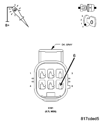
Turn the ignition off.
Using a 12-volt test light connected to 12-volts, probe the (Z42) Ground circuit in the C112 harness connector (PCM side).
Does the test light illuminate brightly?
Yes
- Go To 5
No
- Repair the open in the (Z42) Ground circuit.
- Perform the POWERTRAIN VERIFICATION TEST. (Refer to 9 - ENGINE - STANDARD PROCEDURE)
5. (K454) MDS SOLENOID NO.7 CONTROL CIRCUIT SHORTED TO GROUND (PCM SIDE)
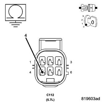
Turn the ignition off.
Disconnect the C3 PCM harness connector.
Measure the resistance between ground and the (K454) MDS Solenoid No.7 Control circuit in the C112 harness connector.
Is the resistance below 100 ohms?
Yes
- Repair the short to ground in the (K454) MDS Solenoid No.7 Control circuit between the PCM harness connector and the C112 harness connector.
- Perform the POWERTRAIN VERIFICATION TEST. (Refer to 9 - ENGINE - STANDARD PROCEDURE)
No
- Go To 6
6. (K454) MDS SOLENOID NO.7 CONTROL CIRCUIT OPEN (PCM SIDE)
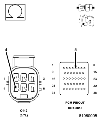
CAUTION: Do not probe the PCM harness connectors. Probing the PCM harness connectors will damage the PCM terminals resulting in poor terminal to pin connection. Install Miller Special Tool #8815 to perform diagnosis.
Measure the resistance of the (K454) MDS Solenoid No.7 Control circuit from the C112 harness connector to the appropriate terminal of special tool #8815.
Is the resistance below 5.0 ohms?
Yes
- Replace and program the Powertrain Control Module in accordance with the service information.
- Perform the POWERTRAIN VERIFICATION TEST. (Refer to 9 - ENGINE - STANDARD PROCEDURE)
No
- Repair the open in the (K454) MDS Solenoid No.7 Control circuit between the C112 harness connector and the PCM harness connector.
- Perform the POWERTRAIN VERIFICATION TEST. (Refer to 9 - ENGINE - STANDARD PROCEDURE)
7. MDS SOLENOID 7
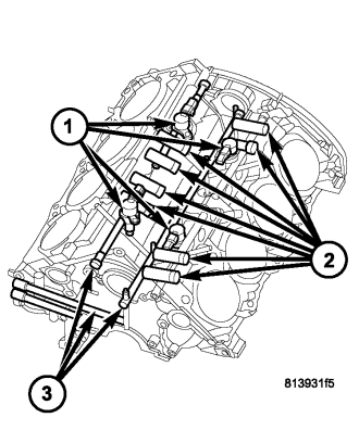
Turn the ignition off.
Remove the Intake Manifold per Service Information.
Reconnect the C3 PCM harness connector.
Turn the ignition on.
With the scan tool actuate the MDS Solenoid 7.
Can you feel and hear the Solenoid Actuating?
Yes
- Go To 8
No
- Remove the Solenoid (1) and check for any debris that may be blocking the oil passages (3) to the Solenoid. If the passages are clogged, clean the passages and replace the MDS Solenoid 7. If the passages are not clogged with debris, replace the MDS Solenoid 7.
8. OIL PASSAGES RESTRICTED
Turn the ignition off.
Remove both Solenoids on Bank 1 of the engine block.
Remove the Bank 1 Cylinder Head per Service Information.
Remove the Lifters from the right engine bank.
Inspect the oil passages to the Solenoids and from the Solenoids to the lifters.
Are the passages blocked?
Yes
- Clean the oil passages as necessary. If the entire engine is restricted disassembly of the entire engine block may be necessary.
No
- Replace both sets of lifters if no other possible causes remain.