GEAR
DESCRIPTION
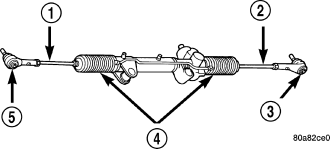
A rack and pinion steering gear is made up of two main components, the pinon shaft and the rack. The gear cannot be adjusted or internally serviced. If a malfunction or a fluid leak occurs, the gear must be replaced as an assembly.
OPERATION
The steering column intermediate shaft is attached to the gear pinion. The rotation of the pinion moves the gear rack from side-to-side. This lateral action of the rack pushes and pulls the tie rods, which are connected to the steering knuckles to change the direction of the front wheels.
REMOVAL
CAUTION: Steering column module is centered to the vehicles steering system. Failure to keep the system and steering column module centered and locked/inhibited from rotating can result in steering column module damage. (Refer to 8 - ELECTRICAL/RESTRAINTS/CLOCKSPRING - STANDARD PROCEDURE).
1. Place the front wheels in the straight ahead position with the steering wheel centered and locked with a steering wheel lock.
2. Drain or siphon the power steering system.
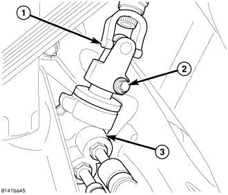
3. Remove the column coupler shaft bolt (2) and remove the shaft from the gear (3).
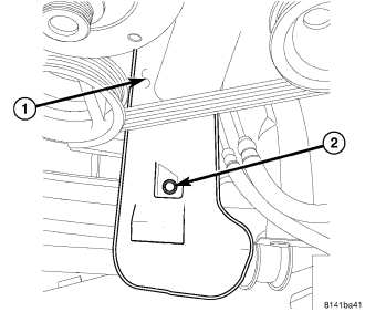
4. Remove the oil drip tray (1).
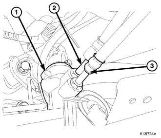
5. Remove the pressure line (2) at the gear (1).
6. Remove the return line (3) at the gear (1).
7. Raise and support the vehicle.
8. Remove the front tires.
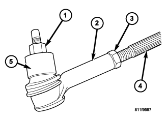
9. Loosen the tie rod end jam nuts (3).
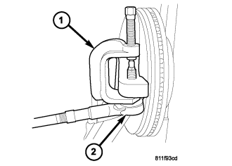
10. Remove the outer tie rod end nut and separate the tie rod (2) from the knuckle using special tool #8677 puller (1).
11. Remove the front splash shield.
12. 4X4 Only - Remove the front axle (Refer to 3 - DIFFERENTIAL & DRIVELINE/FRONT AXLE - REMOVAL).
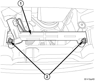
13. Remove the two steering gear mounting bolts (2).
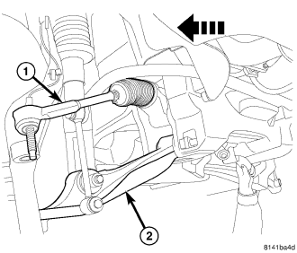
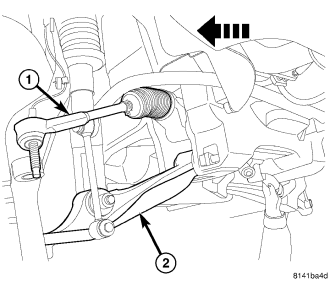
14. Move the gear (1) to the full right position to allow clearance over the control arm (2) then lower the gear down, then turn the gear to the full left position to allow clearance then remove from the vehicle.
15. Remove the outer tie rod ends from the steering gear (if needed).
INSTALLATION
CAUTION: Steering column module is centered to the vehicles steering system. Failure to keep the system and steering column module centered and locked/inhibited from rotating can result in steering column module damage. (Refer to 8 - ELECTRICAL/RESTRAINTS/CLOCKSPRING - STANDARD PROCEDURE).
1. Install the outer tie rod ends. (if removed).
2. Position the steering gear (1) back into the vehicle the same way it was removed.
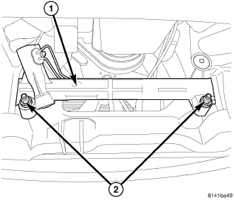
3. Install the Steering gear mounting nuts (2) Tighten to 244 N·m (180 ft. lbs.).
4. Install the front splash shield.
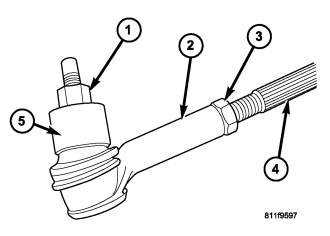
5. Install the outer tie rod ends jam nuts (3) (loose).
6. Install the outer tie rod ends (2) to the knuckle (5) and tighten the tie rod end nut (1) to 95 N·m (70 ft. lbs.).
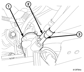
7. Install the pressure and return hoses (2&3) to the steering gear (1) and tighten to 28 N·m (21 ft. lbs.).
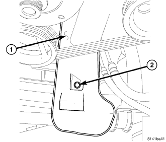
8. Install the oil filter drip tray (1).
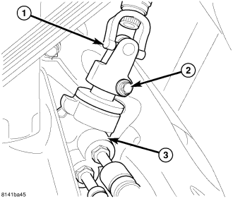
9. Install the column coupler shaft into the lower coupling (1) and install a new bolt (2), Tighten to 49 N·m (36 ft. lbs.).
10. Install the front axle housing unit (Refer to 3 - DIFFERENTIAL & DRIVELINE/FRONT AXLE - C200FE - INSTALLATION). 4x4 ONLY
11. Install the wheel and tire assembly.
12. Remove the support and lower the vehicle.
13. Remove the steering wheel lock.
14. Fill the power steering pump (Refer to 19 - STEERING/PUMP - STANDARD PROCEDURE).
15. Set the toe. (Refer to 2 - SUSPENSION/WHEEL ALIGNMENT - STANDARD PROCEDURE).