TURN SIGNAL CANCEL CAM
DESCRIPTION
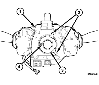
The turn signal cancel cam (3) is concealed within the steering column. The cam consists of two lobes (2) and integral latch features on a molded plastic ring that is snapped into the lower hub of the clockspring rotor, which is integral to the Steering Control Module (SCM) (1). The housing of the SCM also contains the clockspring mechanism and is secured to the top of the steering column just below the steering wheel where it remains stationary. The rotor of the clockspring mechanism, including the turn signal cancel cam rotates with the steering wheel.
The turn signal cancel cam can be separated from the clockspring rotor and is available for individual service replacement. The turn signal cancel cam cannot be adjusted or repaired and, if ineffective or damaged, the cam must be replaced.
OPERATION
When the left multi-function switch control stalk is moved to a latched turn signal position, a turn signal cancel actuator is extended from the inside surface of the left multi-function switch housing toward the turn signal cancel cam. As the steering wheel is rotated to complete the turn, one of the two cam lobes will contact the actuator, automatically cancelling the turn signal event and releasing the latched left multi-function switch control stalk to the neutral position.
REMOVAL
WARNING: To avoid personal injury or death, on vehicles equipped with airbags, disable the supplemental restraint system before attempting any steering wheel, steering column, airbag, seat belt tensioner, impact sensor, or instrument panel component diagnosis or service. Disconnect and isolate the battery negative (ground) cable, then wait two minutes for the system capacitor to discharge before performing further diagnosis or service. This is the only sure way to disable the supplemental restraint system. Failure to take the proper precautions could result in accidental airbag deployment.
NOTE: Before starting this procedure, be certain to turn the steering wheel until the front wheels are in the straight-ahead position and that the entire steering system is locked or inhibited from rotation.
1. Place the front wheels in the straight-ahead position.
2. Remove the Steering Control Module (SCM) from the steering column. (Refer to 8 - ELECTRICAL/ELECTRONIC CONTROL MODULES/STEERING CONTROL MODULE - REMOVAL).
NOTE: The latch features of the turn signal cancel cam are brittle. If the cam will be reused, use care not to break the latch features when prying.
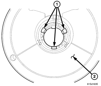
3. From the face of the SCM, use a trim stick or another suitable wide flat-bladed tool to gently pry and disengage each of the three latch features (1) that secure the turn signal cancel cam to the clockspring rotor (2).
4. Remove the cam from the back of the SCM.
INSTALLATION
WARNING: To avoid personal injury or death, on vehicles equipped with airbags, disable the supplemental restraint system before attempting any steering wheel, steering column, airbag, seat belt tensioner, impact sensor, or instrument panel component diagnosis or service. Disconnect and isolate the battery negative (ground) cable, then wait two minutes for the system capacitor to discharge before performing further diagnosis or service. This is the only sure way to disable the supplemental restraint system. Failure to take the proper precautions could result in accidental airbag deployment.
1. Position the alignment hole in the turn signal cancel cam (3) over the alignment pin (4) of the clockspring rotor on the back of the Steering Control Module (SCM) housing (1).
2. Using hand pressure, press the cam firmly and evenly onto the rotor until each of the three latch features of the cam is fully engaged.
3. Reinstall the SCM onto the steering column. (Refer to 8 - ELECTRICAL/ELECTRONIC CONTROL MODULES/STEERING CONTROL MODULE - INSTALLATION).