MODULE-STEERING CONTROL
DESCRIPTION
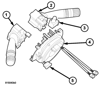
This vehicle is equipped with a Steering Control Module (SCM) (4) that houses an integral, internal clockspring. On some vehicles, the SCM also includes an integral, internal Steering Angle Sensor (SAS). The SCM is secured near the top of the steering column below the steering wheel and is completely concealed beneath the steering column shrouds. The SCM is installed as a modular unit that supports the left (lighting) multi-function switch (1), the right (wiper) multi-function switch (2), the hazard switch (3) and the turn signal cancel cam. The controls for each of the switches extend through appropriate clearance holes provided in the steering column shrouds.
The microprocessor-based SCM utilizes integrated circuitry and information carried on the Controller Area Network (CAN) data bus along with several hard wired analog and multiplexed inputs to monitor both the right and left multi-function switches, the ignition switch, the horn switch, the speed control switches and the remote radio switches. In response to those inputs, the internal circuitry and programming of the SCM allow it to control and integrate many electronic functions and features of the vehicle through both hard wired outputs and the transmission of electronic message outputs to other electronic modules in the vehicle over the CAN data bus. (Refer to 8 - ELECTRICAL/ELECTRONIC CONTROL MODULES/COMMUNICATION - DESCRIPTION - CAN BUS).
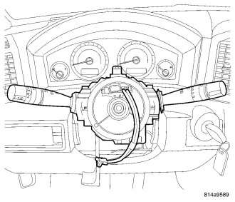
The SCM circuitry, the clockspring, and the SAS are all contained within a flat, round molded plastic case. The back (instrument panel side) of the case has an integral mounting bracket that is secured to the stationary steering column housing with two screws. The back of the case also features a total of five integral fixed connector receptacles. The three upper receptacles are direct interface connectors for the hazard and multi-function switches and are concealed when these switches are mounted. The two lower receptacles connect the SCM to the vehicle electrical system through two take outs and connectors of the instrument panel wire harness.
The face of the SCM case consists of the rotating clockspring rotor with two integral connector receptacles and two pigtail wires with connectors located near the top. One receptacle receives the connector from the remote radio switches, and the other receives the connector from the horn switch and the speed control switches. The two pigtail wires contain the multistage driver airbag squib circuits. The turn signal cancel cam (not shown) extends from the back of the SCM case but is secured to the hub of the clockspring rotor and is keyed to the steering shaft so that it rotates the clockspring rotor with the steering wheel rotation.
A service replacement SCM is shipped with the clockspring pre-centered and with a molded plastic locking pin installed. The locking pin secures the centered clockspring rotor to the SCM case during shipment and handling, but must be removed after the SCM is installed on the steering column and before the steering wheel is installed. (Refer to 8 - ELECTRICAL/RESTRAINTS/CLOCKSPRING - STANDARD PROCEDURE - CLOCKSPRING CENTERING). The service replacement clockspring is also shipped in a standard configuration and must be electronically configured for certain optional equipment before these features will be operational. This optional equipment includes: automatic headlamps, front fog lamps, rear fog lamps, and SAS. Using a diagnostic scan tool, follow the programming steps outlined for CONFIGURE SCM under MISCELLANEOUS FUNCTIONS for the SCM/STEERING CONTROL MODULE menu item as appropriate.
The SCM has programmable memory that can be reprogrammed using a diagnostic scan tool and Flash reprogramming procedures. The SCM cannot be adjusted or repaired. If ineffective or damaged the entire SCM including the integral clockspring and, if the vehicle is so equipped, the SAS must be replaced. The left and right multi-function switches, the hazard switch and the turn signal cancel cam can be removed from and are serviced separately from the SCM.
OPERATION
The Steering Control Module (SCM) contains the clockspring and a microprocessor. On some vehicles, it also contains the Steering Angle Sensor (SAS). The SCM communicates over the Controller Area Network (CAN) data bus with other electronic modules in the vehicle and a diagnostic scan tool connected to the 16-way Data Link Connector (DLC).
The SCM is connected to a fused B(+) circuit and receives a path to ground at all times. These connections allow it to remain functional regardless of the ignition switch position. The driver airbag squib circuits of the clockspring, the speed control switch circuits and the hazard switch circuits pass through the SCM, but the SCM does not monitor, and has no control outputs related to these circuits. Any other input to the SCM that would cause a vehicle system to function but does not require that the ignition switch be in the ON position, such as turning ON the lights or sounding the horn, prompts the SCM to wake up and transmit on the CAN data bus.
The following paragraphs briefly describe the SCM responses to the various hard wired inputs it receives.
- Horn Switch - The horn switch is an input to the SCM. The SCM provides a reference input to the horn switch at all times and monitors the horn switch status on a second circuit. When the horn switch is closed, the SCM transmits an electronic horn switch status message over the CAN data bus. The Front Control Module (FCM) in the engine compartment controls horn relay operation based upon this status message from the SCM.
- Ignition Switch - The ignition switch is an input to the SCM. The SCM provides a reference input to a multiplexed circuit within the ignition switch and monitors the switch status on a second circuit to determine the switch position. The SCM then transmits the appropriate electronic ignition switch status messages to other electronic modules over the CAN data bus. The SCM can also detect a short or open in the switch by monitoring the return input and will transmit an electronic Signal Not Available (SNA) message when a fault is detected.
- Left Multi-Function Switch - The left (lighting) multi-function switch provides several inputs to the SCM. The SCM provides reference inputs to the turn signal, beam select, exterior lighting and interior lighting controls of the left multi-function switch at all times and monitors the status of the switches on return circuits. The SCM then transmits the appropriate electronic switch status messages to other electronic modules over the CAN data bus. The SCM can also detect a shorted, open or stuck switch in each of the switch controls (except front fog lamps) by monitoring the return input and will transmit an electronic SNA message when a fault is detected. In general, the FCM in the engine compartment controls all exterior lighting operation and the ElectroMechanical Instrument Cluster (EMIC) (also referred to as Cab Compartment Node/CCN) controls all interior lighting operation based upon the various electronic switch status messages from the SCM.
- Remote Radio Switches - The steering wheel mounted remote radio controls provide inputs to the SCM. The SCM provides a reference input to a multiplexed circuits within the switches and monitors the switch status on a second circuit to determine both switch positions. The SCM then transmits the appropriate electronic remote radio switch status messages to other electronic modules over the CAN data bus. The SCM can also detect an open or stuck switch by monitoring the return input and will transmit an electronic SNA message when a fault is detected. The radio receiver controls its own operation based upon the electronic remote radio switch status messages from the SCM.
- Right Multi-Function Switch - The right (wiper) multi-function switch provides several inputs to the SCM. The SCM provides reference inputs to the front wiper/washer and rear wiper/washer controls of the right multi-function switch at all times and monitors the status of the switches on return circuits. The SCM then transmits the appropriate electronic switch status messages to other electronic modules over the CAN data bus. The SCM also provides two hard wired high side driver outputs to the rear wiper motor to control the rear wiper ON and DELAY functions. The SCM can detect a shorted, open or stuck switch in each of the switch controls by monitoring the return input and will transmit an electronic SNA message when a fault is detected. The FCM in the engine compartment controls wiper on/off, wiper high/low and rear wiper relay operation based upon the electronic switch status messages from the SCM.
- Steering Angle Sensor - Vehicles equipped with an optional Electronic Stability Program (ESP) system have a Steering Angle Sensor (SAS) and a second, dedicated microprocessor integral to the SCM. The SAS monitors the steering direction/angle and the rate of steering wheel rotation, then the SCM transmits electronic messages with this data to other electronic modules in the vehicle over the CAN data bus. The SCM can detect an ineffective SAS and will transmit an electronic SNA message when a fault is detected. When an SCM is installed into a vehicle without properly centering and locking the entire steering system, the SAS data does not agree with the true position of the steering system and causes the ESP system to shut down. This can also damage the clockspring without any immediate malfunction. Unlike some other DaimlerChrysler vehicles, this SAS never requires calibration. (Refer to 8 - ELECTRICAL/RESTRAINTS/CLOCKSPRING - STANDARD PROCEDURE - CLOCKSPRING CENTERING). Determining if the clockspring/steering angle sensor is centered is also possible electrically using the diagnostic scan tool. Steering wheel position is displayed as ANGLE with a range of up to 900 degrees. Refer to the appropriate menu item on the diagnostic scan tool.
The SCM will store fault information in the form of a Diagnostic Trouble Code (DTC) in SCM memory if a malfunction is detected. Any stored DTC can be retrieved using a diagnostic scan tool.
The hard wired circuits between components related to the SCM may be diagnosed using conventional diagnostic tools and procedures. Refer to the appropriate wiring information. The wiring information includes wiring diagrams, proper wire and connector repair procedures, details of wire harness routing and retention, connector pin-out information and location views for the various wire harness connectors, splices and grounds.
However, conventional diagnostic methods will not prove conclusive in the diagnosis of the SCM or the electronic controls or communication between modules and other devices that provide some features of the SCM. The most reliable, efficient, and accurate means to diagnose the SCM or the electronic controls and communication related to SCM operation requires the use of a diagnostic scan tool. Refer to the appropriate diagnostic information.
REMOVAL
WARNING: To avoid personal injury or death, on vehicles equipped with airbags, disable the supplemental restraint system before attempting any steering wheel, steering column, airbag, seat belt tensioner, impact sensor, or instrument panel component diagnosis or service. Disconnect and isolate the battery negative (ground) cable, then wait two minutes for the system capacitor to discharge before performing further diagnosis or service. This is the only sure way to disable the supplemental restraint system. Failure to take the proper precautions could result in accidental airbag deployment.
CAUTION: A service replacement Steering Control Module (SCM) is shipped with the clockspring pre-centered and with a molded plastic locking pin installed. This locking pin should not be removed until the SCM has been installed on the steering column. If the locking pin is removed before the SCM is installed on a steering column, the clockspring centering procedure must be performed. (Refer to 8 - ELECTRICAL/RESTRAINTS/CLOCKSPRING - STANDARD PROCEDURE - CLOCKSPRING CENTERING).
NOTE: Before starting this procedure, be certain to turn the steering wheel until the front wheels are in the straight-ahead position and that the entire steering system is locked or inhibited from rotation.
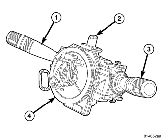
1. Place the front wheels in the straight ahead position.
2. Disconnect and isolate the battery negative cable.
3. Remove the driver airbag from the steering wheel. (Refer to 8 - ELECTRICAL/RESTRAINTS/DRIVER AIRBAG - REMOVAL).
4. Disconnect the steering wheel wire harness connectors from the upper clockspring rotor connector receptacles.
CAUTION: Be certain that the screws that secure the steering wheel puller to the steering wheel are fully engaged in the steering wheel armature without passing through the steering wheel and damaging the clockspring.
5. Remove the steering wheel from the steering column. (Refer to 19 - STEERING/COLUMN/STEERING WHEEL - REMOVAL).
6. Remove the shrouds from the steering column. (Refer to 19 - STEERING/COLUMN/SHROUD - REMOVAL).
7. Remove the right (wiper ) multi-function switch (3) from the SCM (4). (Refer to 8 - ELECTRICAL/WIPERS/WASHERS/RIGHT MULTI-FUNCTION SWITCH - REMOVAL).
8. Remove the left (lighting) multi-function switch (1) from the SCM. (Refer to 8 - ELECTRICAL/LAMPS/LIGHTING - EXTERIOR/MULTI-FUNCTION SWITCH - REMOVAL).
9. Remove the hazard switch (2) from the SCM. (Refer to 8 - ELECTRICAL/LAMPS/LIGHTING - EXTERIOR/HAZARD SWITCH - REMOVAL).
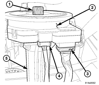
10. Disconnect the two instrument panel wire harness connectors (3 and 4) from the two connector receptacles located below the steering column (5) on the back of the SCM case (2).
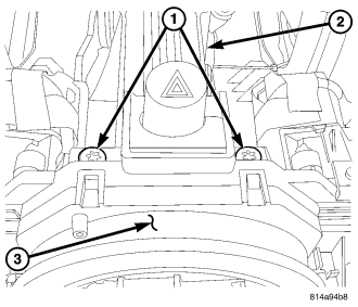
11. Remove the two screws (1) that secure the SCM (3) to the steering column housing (2).
12. Remove the SCM from the steering column housing. The SCM/clockspring cannot be repaired. It must be replaced if ineffective or damaged, or if the driver airbag has been deployed.
13. If the removed SCM is to be reused, be certain to secure the clockspring rotor to the SCM case to maintain clockspring centering until it is reinstalled on the steering column. If clockspring centering is not maintained, the clockspring must be centered again before it is reinstalled. (Refer to 8 - ELECTRICAL/RESTRAINTS/CLOCKSPRING - STANDARD PROCEDURE - CLOCKSPRING CENTERING).
14. Remove the turn signal cancel cam from the clockspring rotor of the SCM. (Refer to 8 - ELECTRICAL/LAMPS/LIGHTING - EXTERIOR/TURN SIGNAL CANCEL CAM - REMOVAL).
INSTALLATION
WARNING: To avoid personal injury or death, on vehicles equipped with airbags, disable the supplemental restraint system before attempting any steering wheel, steering column, airbag, seat belt tensioner, impact sensor, or instrument panel component diagnosis or service. Disconnect and isolate the battery negative (ground) cable, then wait two minutes for the system capacitor to discharge before performing further diagnosis or service. This is the only sure way to disable the supplemental restraint system. Failure to take the proper precautions could result in accidental airbag deployment.
CAUTION: A service replacement Steering Control Module (SCM) is shipped with the clockspring pre-centered and with a molded plastic locking pin installed. This locking pin should not be removed until the SCM has been installed on the steering column. If the locking pin is removed before the SCM is installed on a steering column, the clockspring centering procedure must be performed. (Refer to 8 - ELECTRICAL/RESTRAINTS/CLOCKSPRING - STANDARD PROCEDURE - CLOCKSPRING CENTERING).
NOTE: Before starting this procedure, be certain to turn the steering wheel until the front wheels are in the straight-ahead position and that the entire steering system is locked or inhibited from rotation.
1. Reinstall the turn signal cancel cam onto the clockspring rotor of the SCM. (Refer to 8 - ELECTRICAL/LAMPS/LIGHTING - EXTERIOR/TURN SIGNAL CANCEL CAM - INSTALLATION).
2. While holding the centered clockspring rotor and the SCM case (3) stationary in relation to each other, carefully slide the SCM down over the steering column upper shaft.
3. Install and tighten the two screws (1) that secure the SCM to the steering column housing (2). Tighten the screws to 2 N·m (20 in. lbs.).
4. Reconnect the two instrument panel wire harness connectors (3 and 4) to the two connector receptacles located below the steering column (5) on the back of the SCM case (2).
5. Reinstall the hazard switch (2) onto the SCM (4). (Refer to 8 - ELECTRICAL/LAMPS/LIGHTING - EXTERIOR/HAZARD SWITCH - INSTALLATION).
6. Reinstall the left (lighting) multi-function switch (1) onto the SCM. (Refer to 8 - ELECTRICAL/LAMPS/LIGHTING - EXTERIOR/MULTI-FUNCTION SWITCH - INSTALLATION).
7. Reinstall the right (wiper ) multi-function switch (3) onto the SCM. (Refer to 8 - ELECTRICAL/WIPERS/WASHERS/RIGHT MULTI-FUNCTION SWITCH - INSTALLATION).
8. Reinstall the shrouds onto the steering column. (Refer to 19 - STEERING/COLUMN/SHROUD - INSTALLATION).
9. If a new SCM has been installed, remove the plastic locking pin that is securing the clockspring rotor to the SCM case to maintain clockspring centering.
10. Reinstall the steering wheel onto the steering column. (Refer to 19 - STEERING/COLUMN/STEERING WHEEL - INSTALLATION).
11. Reconnect the steering wheel wire harness connectors to the upper clockspring rotor connector receptacles. Be certain that the steering wheel wire harness is routed between the steering wheel back trim cover and the steering wheel armature.
12. Reinstall the driver airbag onto the steering wheel. (Refer to 8 - ELECTRICAL/RESTRAINTS/DRIVER AIRBAG - INSTALLATION).
13. Reconnect the battery negative cable.
NOTE: Whenever the SCM is replaced with a new unit, it is necessary to configure the new module for certain optional equipment in the vehicle using a diagnostic scan tool. Follow the programming steps outlined in the diagnostic scan tool for “Configure SCM” under “Miscellaneous Functions” for the “SCM/Steering Control Module” menu item as appropriate.