STANDARD PROCEDURE
UNDERBODY LINE REPAIR
WARNING: Refer to the applicable warnings and cautions for this system before performing the following operation (refer to 24 - HEATING & AIR CONDITIONING/PLUMBING - FRONT - WARNING) and (refer to 24 - HEATING & AIR CONDITIONING/PLUMBING - FRONT - CAUTION). Failure to follow the warnings and cautions could result in possible personal injury or death.
WARNING: This procedure is intended for underbody line repair only. Use of the connector fittings and A/C Line Repair Tool Kit 8456-A on any other type of vehicle tubing could cause tube failure resulting in possible personal injury or death.
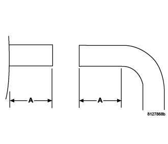
1. If repairing an underbody refrigerant line, recover the refrigerant from the refrigerant system (refer to 24 - HEATING & AIR CONDITIONING/PLUMBING - FRONT - STANDARD PROCEDURE - REFRIGERANT SYSTEM RECOVERY).
2. If repairing an underbody coolant line, drain the engine cooling system (refer to 7 - COOLING - STANDARD PROCEDURE - COOLING SYSTEM DRAIN).
3. Disconnect and isolate the negative battery cable.
4. Raise and support the vehicle.
5. Remove the underbody mounting brackets as necessary to gain access to the underbody line(s) needing repair (refer to 24 - HEATING & AIR CONDITIONING/PLUMBING - REAR/LINES-UNDERBODY - REMOVAL).
6. Mark the cut location(s) on the underbody line(s) needing repair. Check the Tube Length chart for the minimum amount of straight tube required (dimension A) for proper connector fitting installation.
7. Using a small pipe cutter or another suitable tool, carefully cut the underbody line(s) needing repair at the location(s) previously marked.
| Tube Size | Minimum Tube Length Required | |
| Dimension A Standard Installation | Dimension A Jaw Reversed Installation | |
| 3/8 in | 28.5 mm (1 1/8 in) | 19 - 28.5 mm (3/4 - 1 1/8 in) |
| 1/2 in | 28.5 mm (1 1/8 in) | 19 - 28.5 mm (3/4 - 1 1/8 in) |
| 5/8 in | 31.7 mm (1 1/4 in) | 22.2 - 31.7 mm (7/8 - 1 1/4 in) |
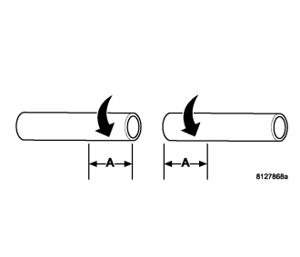
8. Size a replacement line, same size diameter and length as the portion of the line(s) removed.
NOTE: A minimum of 28.5 mm (3/4 in) of the line end must be cleaned in order for the connector fitting to properly seal the repair area.
9. Clean the ends of the line(s) a minimum of 28.5 mm (3/4 in) (dimension A) using the Scotch-Bright pad provided with A/C Line Repair Tool Kit 8456-A. Clean the line end(s) with a rotational motion around the line to avoid longitudinal scratches in the line.
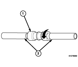
10. Select the proper connector fitting (1) for the size of the underbody line being repaired. Refer to the Connector Fitting chart.
11. Apply one drop of Lokprep sealing compound provided with A/C Line Repair Tool Kit 8456-A onto each line end (2).
12. Insert the line ends into the selected connector fitting and rotate the connector fitting a complete turn to evenly distribute the sealing compound.
| Description | Mopar Part Number |
| 3/8 in | 5069 002AA |
| 1/2 in | 5069 003AA |
| 5/8 in | 5069 004AA |
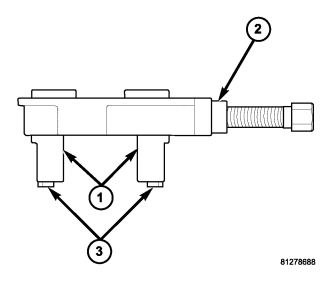
13. Select the proper size jaws (1) for the line being repaired from the A/C Line Repair Tool Kit 8456-A. Refer to the Jaw Size chart.
14. Assemble the jaws into the tool body (Special Tool 8456-3 in Kit 8456-A) (2).
a. For standard installation, install the jaws with the rubber gripping pads (3) facing outward. Refer to Tube Length chart.
b. For reversed installation, remove the rubber gripping pads and install the jaws with the rubber gripping pad area facing inward. Refer to Tube Length chart.
| Description | Miller Part Number |
| 3/8 in | 8456-1 |
| 1/2 in | 8456-4 |
| 5/8 in | 8456-2 |
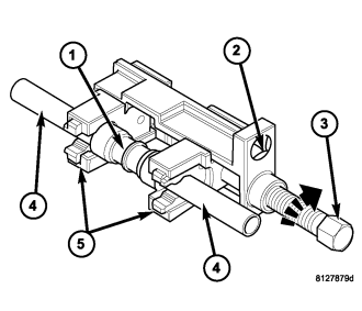
NOTE: The connector fitting ends must be positioned into the counterbore of the jaws in order for the connector fitting to properly seal the repair area.
15. Install the connector fitting (1) and the line ends (4) into the counterbore of the jaws (5).
16. Hold the tool body (Special Tool 8456-3 in Kit 8456-A) (2) with a 3/8 inch breaker bar and turn the forcing screw (3) clockwise.
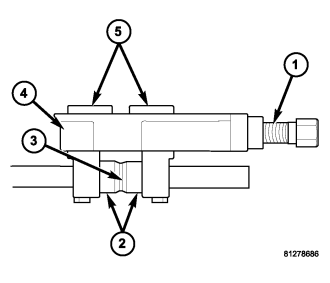
NOTE: The lines must be kept fully inserted into the connector fitting to obtain a leak free joint.
17. Turn the forcing screw (1) clockwise until both connector fitting collars (2) have bottomed out on the center shoulder of the connector (3).
18. Loosen the forcing screw and remove the tool body (Special Tool 8456-3 in Kit 8456-A) (4) and the jaws (5) from the repaired line(s).
19. Install the underbody mounting brackets as necessary (refer to 24 - HEATING & AIR CONDITIONING/PLUMBING - REAR/LINES-UNDERBODY - INSTALLATION).
20. Lower the vehicle.
21. Reconnect the negative battery cable.
22. If repairing an underbody coolant line, refill the engine cooling system (refer to 7 - COOLING - STANDARD PROCEDURE - COOLING SYSTEM REFILL).
23. If repairing an underbody refrigerant line, evacuate and charge the refrigerant system (refer to 24 - HEATING & AIR CONDITIONING/PLUMBING - FRONT - STANDARD PROCEDURE - REFRIGERANT SYSTEM EVACUATE) and (refer to 24 - HEATING & AIR CONDITIONING/PLUMBING - FRONT - STANDARD PROCEDURE - REFRIGERANT SYSTEM CHARGE).