MOTOR - POWER LIFTGATE DRIVE UNIT
DESCRIPTION
Vehicles equipped with a power liftgate, utilize a liftgate motor. The liftgate motor is a simple DC motor that can be operated in forward or reverse, depending on the voltage polarity supplied by the power liftgate control module. The motor is attached to the power liftgate drive unit by three retaining bolts. (Refer to 8 - ELECTRICAL/POWER DOORS/DRIVE UNIT - DESCRIPTION) for a complete description of the entire drive unit assembly and components.
The power liftgate motor cannot be repaired or adjusted, and if found to be inoperative the motor must be replaced. (Refer to 8 - ELECTRICAL/POWER DOORS/MOTOR - REMOVAL) for detailed instructions.
OPERATION
LIFTGATE IS CLOSED
The power liftgate open command can be initiated by either one press of the power liftgate overhead console switch or two presses of the key fob power liftgate button. The overhead console switch is hardwired to the power liftgate control module, where as the key fob signal is sent out on the Controller Area Network (CAN) Data Bus circuit. This signal is detected by the power liftgate control module. The power liftgate control module then interprets the information to confirm safety requirements are met. The control module will then signal the liftgate mounted latch assembly to release the liftgate from its primary closed and latched position to the ajar and movable position. Once the liftgate control module detects “liftgate ajar”, the control module will provide 12v power to the liftgate motor. The motor will then rotate the drive unit moving the liftgate into the full open position.
LIFTGATE IS OPEN
The power liftgate close command can be initiated by either one press of the power liftgate overhead console switch or two presses of the key fob power liftgate button. The overhead console switch is hardwired to the power liftgate control module, where as the key fob signal is sent out on the Controller Area Network (CAN) Data Bus circuit. This signal is detected by the power liftgate control module. The power liftgate control module then interprets the information to confirm safety requirements are met. The control module will then provide 12v power to the liftgate motor. The motor will then rotate the drive unit moving the liftgate into the closed position. Once the liftgate mounted latch reaches the body mounted striker assembly, the power latch takes over to cinch the liftgate to the fully closed and latched position.
If an obstacle is encountered during a power open or close cycle, the power liftgate control module will automatically reverse direction of the liftgate to prevent vehicle damage or personal injury.
REMOVAL
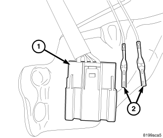
1. Open the liftgate.
2. Disconnect and isolate the battery negative cable.
3. Remove the power liftgate drive unit assembly from the vehicle, (Refer to 8 - ELECTRICAL/POWER DOORS/DRIVE UNIT - REMOVAL).
CAUTION: Mark the position of the two full open switch wire terminals (2) in relation to their location in the liftgate drive unit wire connector (1).
4. Using an appropriate wire terminal tool, carefully remove the full open switch wire terminals (2) from the liftgate drive unit connector (1).
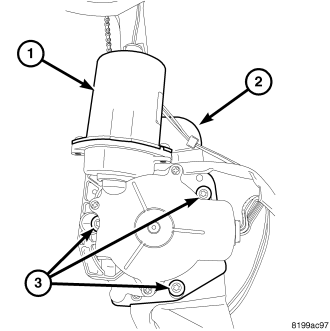
5. Remove the three motor retaining screws (3) and remove the motor (1) from the drive unit assembly (2).
INSTALLATION
1. Carefully line-up the motor (1) with the chain drive gear and slide the motor assembly onto the drive unit assembly (2). Be certain the gears are properly meshed.
2. Install the three motor retaining screws (3). Tighten the screws to 6 N·m (50 in. lbs.).
3. Insert the full open switch wire terminals (2) into the liftgate drive unit connector (1) ensuring the proper terminal location as noted in the motor removal procedure.
4. Install the power liftgate drive unit assembly on the vehicle, (Refer to 8 - ELECTRICAL/POWER DOORS/DRIVE UNIT - INSTALLATION).
5. Connect the battery negative cable.
6. Using an appropriate scan tool, check and erase any power liftgate control module diagnostic trouble codes.
7. Perform the power liftgate learn cycle, (Refer to 8 - ELECTRICAL/POWER DOORS - STANDARD PROCEDURE - POWER LIFTGATE LEARN CYCLE).
8. Verify power liftgate system operation.