SWITCH - FULL OPEN
DESCRIPTION
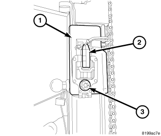
Vehicles equipped with a power liftgate system utilize a full open switch (2). The full open switch is comprised of two main components, the micro-switch and plastic bracket. The full open switch and bracket assembly are located on the power liftgate drive unit (1) and is used to signal the power liftgate control module when the liftgate is approaching the full open position. Two wires connect the full open switch to the drive unit's main electrical connector.
The full open switch cannot be adjusted or repaired and if found to be inoperative or damaged, must be replaced. (Refer to 8 - ELECTRICAL/POWER DOORS/SWITCH - REMOVAL).
OPERATION
When the power liftgate is approaching the full open position, the full open switch's contact arm leaves contact with the moving rack assembly. This releases the switch and closes the circuit supplied to the power liftgate module. This signals the module that the liftgate is reaching the full open position. The full open switch is a normally closed circuit micro-switch.
REMOVAL
1. Open the liftgate.
2. Disconnect and isolate the battery negative cable.
3. Remove the power liftgate drive unit, (Refer to 8 - ELECTRICAL/POWER DOORS/DRIVE UNIT - REMOVAL).
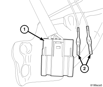
CAUTION: Mark the position of the two full open switch wire terminals (2) in relation to their location in the liftgate drive unit wire connector (1).
4. Using an appropriate wire terminal tool, carefully remove the full open switch wire terminals (2) from the liftgate drive unit connector (1).
5. Remove the full open switch retaining screw (3) from the drive unit assembly (1).
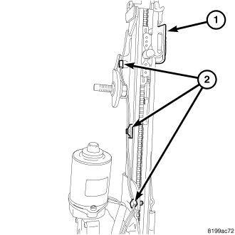
6. Carefully remove the full open switch wire harness routing clips (2) from the power liftgate drive unit assembly (1).
7. Remove the full open switch and wire harness.
INSTALLATION
CAUTION: Be certain the wires are reinstalled in the correct wire cavities. Failure to do so could result in damage to components. Refer to Wiring Diagrams if uncertain.
1. Position the full open switch (2) onto the power liftgate drive unit assembly (1) and install the retaining screw (3).
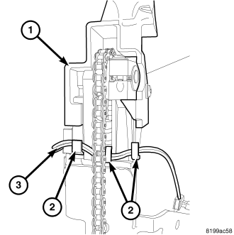
2. Ensure the full open switch wire harness (3) is routed properly through the power liftgate drive unit routing tabs (2).
3. Carefully install the full open switch wire harness routing clips (2) into the power liftgate drive unit assembly (1).
4. Insert the full open switch wire terminals (2) into the liftgate drive unit connector (1) ensuring the proper terminal location as noted in the full open switch removal procedure.
5. Install the power liftgate drive unit assembly on the vehicle, (Refer to 8 - ELECTRICAL/POWER DOORS/DRIVE UNIT - INSTALLATION).
6. Connect the battery negative cable.
7. Using an appropriate scan tool, check and erase any power liftgate control module diagnostic trouble codes.
8. Perform the power liftgate learn cycle, (Refer to 8 - ELECTRICAL/POWER DOORS - STANDARD PROCEDURE - POWER LIFTGATE LEARN CYCLE).
9. Verify power liftgate system operation.