PUMP-WASHER-WINDSHIELD
DESCRIPTION
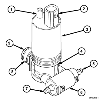
The washer pump/motor unit (3) is located on the outboard side of the washer reservoir, in the left front fender wheel house ahead of the front wheel and the left front wheel house splash shield. A small permanently lubricated and sealed reversible electric motor is coupled to the rotor-type washer pump (4). The use of an integral valve body (6) allows the washer pump/motor unit to provide washer fluid to either the front or the rear washer systems, depending upon the direction of the pump impeller rotation.
A seal flange with a barbed inlet nipple (8) on the pump housing passes through a rubber grommet seal installed in a dedicated mounting hole of the washer reservoir. A removable molded plastic filter screen (9) inserted into the inlet nipple prevents most debris from entering the pump housing. When the pump is installed in the reservoir the front barbed outlet nipple (5) on the pump valve body housing connects the unit to the front washer hose, and the rear barbed outlet nipple (7) connects the unit to the rear washer hose. The letters F and R molded into the valve body housing adjacent to each nipple provide further clarification of the nipple assignments.
The washer pump/motor unit is retained on the reservoir by the interference fit between the barbed pump inlet nipple and the grommet seal, which is a light press fit. The top of the washer pump is also secured to the washer reservoir by the use of a snap post (1) on the motor and a snap post receptacle molded into the reservoir that allows for mounting of the washer pump without the use of fasteners. An integral connector receptacle (2) on the top of the motor housing connects the unit to the vehicle electrical system through a dedicated take out and connector of the headlamp and dash wire harness.
The washer pump/motor unit cannot be repaired. If ineffective or damaged, the entire unit must be replaced.
OPERATION
The washer pump/motor unit features a reversible electric motor. The direction of the motor is controlled by hard wired outputs from the Front Control Module (FCM). When battery current and ground are applied to the two pump motor terminals, the motor rotates in one direction. When the polarity of these connections is reversed, the motor rotates in the opposite direction. When the pump motor is energized, the rotor-type pump pressurizes the washer fluid and forces it through one of the two pump outlet nipples, and into the front or rear washer plumbing.
The FCM controls the hard wired outputs to the pump motor based upon electronic washer request messages received over the Controller Area Network (CAN) data bus from the Steering Control Module (SCM). The SCM monitors a resistor multiplexed input from the front and rear washer switch circuitry contained within the right (wiper) multi-function switch to determine the proper washer request message to send. Whenever the low washer fluid indicator is illuminated, the FCM is programmed to suppress all rear washer requests in order to give priority to the need for forward visibility.
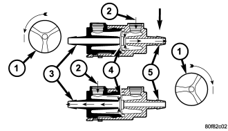
Washer fluid is gravity-fed from the washer reservoir to the inlet port of the washer pump housing. An integral valve body is located in a housing on the outlet port side (2) of the pump housing. A diaphragm (4) in this valve body controls which washer system plumbing receives the washer fluid being pressurized by the pump. When the pump is not operating the diaphragm is biased to close all washer fluid flow in the rear washer system and, in this way it also performs the function of the rear washer system check valve.
When the pump impeller (1) rotates in the counterclockwise direction (viewed from the bottom), the biased diaphragm is sealing off the rear washer system outlet and nipple so the pressurized washer fluid is pushed out through the pump front outlet port and the front washer outlet nipple (5). When the pump impeller rotates in the clockwise direction (viewed from the bottom), pressurized washer fluid is pushed out through the pump rear outlet port and moves the diaphragm to open the rear washer outlet nipple and seal off the front washer outlet nipple, then the pressurized washer fluid is pushed out through the rear washer outlet nipple (3).
The washer pump/motor unit and the hard wired motor control circuits from the FCM may be diagnosed using conventional diagnostic tools and procedures. Refer to the appropriate wiring information. However, conventional diagnostic methods will not prove conclusive in the diagnosis of the washer pump/motor unit or the electronic controls or communication between other modules and devices that provide some features of the front and rear wiper and washer system. The most reliable, efficient, and accurate means to diagnose the washer pump/motor unit or the electronic controls and communication related to washer pump/motor unit operation requires the use of a diagnostic scan tool. Refer to the appropriate diagnostic information.
REMOVAL
NOTE: The washer pump/motor unit may be removed from the washer reservoir without removing the reservoir from the vehicle.
1. Disconnect and isolate the battery negative cable.
2. Turn the steering wheel to move the front wheels to the full left position.
3. Raise and support the vehicle.
4. Remove the plastic push-in fasteners that secure the forward end of the left front wheelhouse splash shield to the inner fender panel and the front fascia. (Refer to 23 - BODY/EXTERIOR/LINER-FENDER AND QUARTER PANEL - REMOVAL).
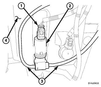
5. Pull the forward end of the left front wheelhouse splash shield away from the inner fender panel and front fascia far enough to access the washer pump/motor unit (2) on the outboard side of the washer reservoir (4) for service.
6. Disconnect the headlamp and dash wire harness connector (1) for the washer pump motor from the motor connector receptacle.
NOTE: To aid in reinstallation, note the installed position of the washer hoses prior to disconnecting them from the washer pump.
7. Disconnect the front and rear washer hoses (3) from the barbed outlet nipples of the washer pump and allow the washer fluid to drain into a clean container for reuse.
8. Grasp the top of the washer pump/motor housing and pull it firmly outward far enough to disengage the snap post on the top of the motor from the receptacle in the reservoir.
9. Grasp the lower part of the washer pump/motor housing and, using a back and forth twisting action, pull the unit outward from the reservoir far enough to disengage the pump inlet nipple from the rubber grommet seal in the reservoir.
10. Remove the rubber grommet seal from the washer pump mounting hole in the reservoir and discard.
INSTALLATION
1. Lubricate a new rubber grommet seal with clean washer fluid and install it into the washer pump mounting hole located in the outboard side of the washer reservoir (4). Always use a new rubber grommet seal on the reservoir.
2. Position the barbed inlet nipple of the washer pump/motor unit (2) to the rubber grommet seal in the reservoir.
3. Using hand pressure, press on the lower part of the washer pump firmly and evenly until the barbed inlet nipple is fully seated in the rubber grommet seal in the reservoir.
4. Align the snap post on the top of the motor housing with the snap post receptacle in the washer reservoir.
5. Using hand pressure, press firmly and evenly on the top of motor housing until the post snaps into the receptacle.
NOTE: Be certain to reconnect the front and rear washer hoses to the proper outlet nipples of the washer pump. Failure to properly connect the hoses will cause the front and rear washer systems to operate incorrectly.
6. Reconnect the front and rear washer hoses (3) to the barbed outlet nipples of the washer pump.
7. Reconnect the headlamp and dash wire harness connector (1) for the washer pump/motor unit to the connector receptacle on the top of the motor.
8. Reinstall the plastic push-in fasteners that secure the left front wheelhouse splash shield to the inner fender panel and the front fascia. (Refer to 23 - BODY/EXTERIOR/LINER-FENDER AND QUARTER PANEL - INSTALLATION).
9. Lower the vehicle.
10. Reconnect the battery negative cable.
11. Refill the washer reservoir with the washer fluid drained during removal.