SENSOR-WASHER FLUID LEVEL
DESCRIPTION
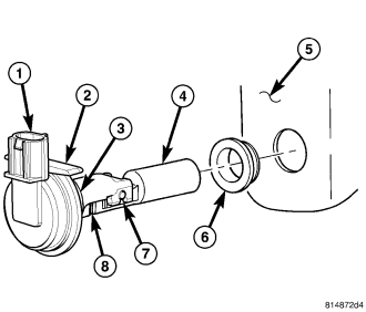
The washer fluid level switch is a single pole, single throw reed-type switch mounted on the left outboard side of the washer reservoir (5), just rearward of the washer pump/motor. Only the molded plastic switch mounting flange (2) and the integral connector receptacle (1) are visible when the switch is installed in the reservoir. A short nipple formation (3) extends from the inner surface of the switch mounting flange, and a barb on the nipple is pressed through a rubber grommet seal (6) installed in the mounting hole of the reservoir.
A small, molded plastic float (4) has two pivot pins (7) near its center that are snapped into two receptacles near the ends of two stanchions that extend toward the float from the nipple formation. A small magnet (8) is secured within the end of the float nearest the nipple, and a reed switch is concealed within the nipple. A diagnostic resistor is connected between the two switch terminals within the switch mounting flange.
The washer fluid level switch cannot be adjusted or repaired. If ineffective or damaged, it must be replaced.
OPERATION
The washer fluid level switch uses a pivoting, oblong float to monitor the level of the washer fluid in the washer reservoir. The float contains a small magnet. When the float pivots, the proximity of this magnet to a stationary reed switch within the nipple formation of the switch changes. When the fluid level in the washer reservoir is at or above the float level, the float moves to a vertical position, the influence of the float magnetic field is removed from the reed switch, and the normally open reed switch contacts open. When the fluid level in the washer reservoir falls below the level of the pivoting float, the float moves to a horizontal position, the influence of the float magnetic field is applied to the reed switch, and the contacts of the normally open reed switch close.
The washer fluid level switch is connected to the vehicle electrical system through a dedicated take out and connector of the headlamp and dash wire harness. The switch is connected in series between a clean ground output of the Front Control Module (FCM) on a sensor return circuit and the washer fluid switch sense input to the FCM. When the switch closes, the FCM senses the ground on the washer fluid switch sense circuit. The FCM is programmed to respond to this input by sending an electronic washer fluid indicator lamp-ON message to the ElectroMechanical Instrument Cluster (EMIC) (also known as the Cab Compartment Node/CCN) over the Controller Area Network (CAN) data bus. The EMIC responds to this message by illuminating the washer fluid indicator, sounding an audible chime tone warning and suppressing requests for rear washer system operation.
The washer fluid level switch and the hard wired circuits between the switch and the FCM may be diagnosed using conventional diagnostic tools and procedures. Refer to the appropriate wiring information. However, conventional diagnostic methods will not prove conclusive in the diagnosis of the washer fluid level switch or the electronic controls or communication between other modules and devices that provide some features of the wiper and washer systems. The most reliable, efficient, and accurate means to diagnose the washer fluid level switch or the electronic controls and communication related to washer fluid level switch operation requires the use of a diagnostic scan tool. Refer to the appropriate diagnostic information.
REMOVAL
NOTE: The washer fluid level switch may be removed from the washer reservoir without removing the reservoir from the vehicle.
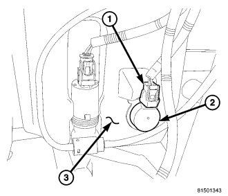
1. Disconnect and isolate the battery negative cable.
2. Turn the steering wheel to move the front wheels to the full left position.
3. Raise and support the vehicle.
4. Remove the plastic push-in fasteners that secure the forward end of the left front wheelhouse splash shield to the inner fender panel and the front fascia. (Refer to 23 - BODY/EXTERIOR/LINER-FENDER AND QUARTER PANEL - REMOVAL).
5. Pull the forward end of the left front wheelhouse splash shield away from the inner fender panel and front fascia far enough to access the washer fluid level switch (2) on the outboard side of the washer reservoir (3) for service.
6. Disconnect the headlamp and dash wire harness connector (1) for the washer fluid level switch from the switch connector receptacle.
NOTE: The pivoting float of the washer fluid level switch must be in a horizontal position within the reservoir in order to be removed. With the reservoir empty and in an upright position, the pivoting float will orient itself to the horizontal position when the switch connector receptacle is pointed straight upwards.
7. Disconnect the front washer hose from the outlet nipple of the washer pump/motor unit and allow the washer fluid to drain into a clean container for reuse.
CAUTION: Care must be taken not to damage the reservoir during washer fluid level switch removal.
8. Using a trim stick or another suitable wide flat-bladed tool, gently pry the barbed nipple of the washer fluid level switch out of the rubber grommet seal in the reservoir.
9. Remove the switch and float from the reservoir.
10. Remove the rubber grommet seal from the mounting hole in the washer reservoir and discard.
INSTALLATION
1. Lubricate a new rubber grommet with clean washer fluid and install it into the washer fluid level switch mounting hole located in the outboard side of the washer reservoir (3).
2. Slide the float through and align the barbed nipple of the switch with the rubber grommet seal in the reservoir. The connector receptacle of the switch should be pointed upward.
3. Press firmly and evenly on the switch (2) using hand pressure until the barbed nipple is fully seated in the rubber grommet seal in the reservoir.
4. Reconnect the headlamp and dash wire harness connector (1) for the washer fluid level switch to the switch connector receptacle.
5. Reconnect the front washer hose to the washer pump/motor unit outlet nipple.
6. Reinstall the plastic push-in fasteners that secure the left front wheelhouse splash shield to the inner fender panel and the front fascia. (Refer to 23 - BODY/EXTERIOR/LINER-FENDER AND QUARTER PANEL - INSTALLATION).
7. Lower the vehicle.
8. Reconnect the battery negative cable.
9. Refill the washer reservoir with the washer fluid drained during removal.