TURBOCHARGER
DESCRIPTION
CAUTION: The turbocharger is a performance part and must not be tampered with. Tampering with the wastegate components can reduce durability by increasing cylinder pressure and thermal loading due to incorrect inlet and exhaust manifold pressure. Poor fuel economy and failure to meet regulatory emissions laws may result. Increasing the turbocharger boost WILL NOT increase engine power.
The turbocharger is an exhaust-driven compressor which increases the pressure and density of the air entering the engine. With the increase of air entering the engine, more fuel can be injected into the cylinders, which creates more power during combustion.
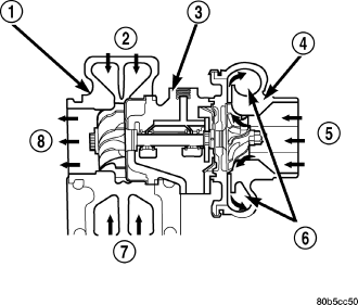
The turbocharger assembly consists of four major component systems :
- Turbine section
- Compressor section
- Bearing housing
- Wastegate
OPERATION
Exhaust gas pressure and energy drive the turbine, which in turn drives a centrifugal compressor that compresses the inlet air, and forces the air into the engine through the charge air cooler and plumbing. Since heat is a by-product of this compression, the air must pass through a charge air cooler to cool the incoming air and maintain power and efficiency.
Increasing air flow to the engine provides:- Improved engine performance
- Improved operating economy
- Altitude compensation
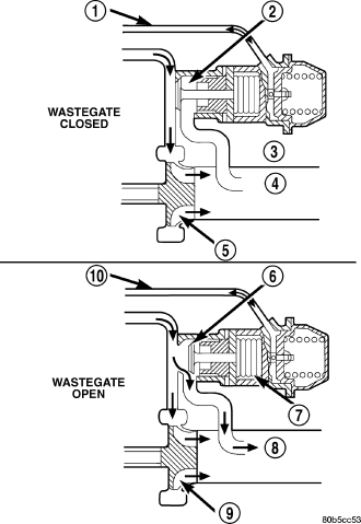
The turbocharger also uses a wastegate, which regulates intake manifold air pressure and prevents over boosting at high engine speeds. When the wastegate valve is closed, all of the exhaust gases flow through the turbine wheel. As the intake manifold pressure increases, the wastegate actuator opens the valve, diverting some of the exhaust gases away from the turbine wheel. This limits turbine shaft speed and air output from the impeller.
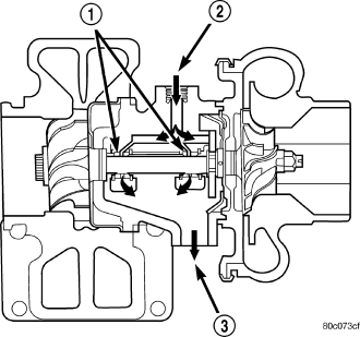
The turbocharger is cooled by engine coolant. The coolant is delivered to the turbocharger by a supply line that connects from engine block to the turbocharger. A coolant return line connects the turbocharger to heater tubes.
The turbocharger is lubricated by engine oil that is pressurized, cooled, and filtered. The oil is delivered to the turbocharger by a supply line that is tapped into the cylinder block. The oil travels into the bearing housing, where it lubricates the shaft and bearings. A return pipe at the bottom of the bearing housing, routes the engine oil back to the crankcase.
The most common turbocharger failure is bearing failure related to repeated hot shutdowns with inadequate “cool-down” periods. A sudden engine shut down after prolonged operation will result in the transfer of heat from the turbine section of the turbocharger to the bearing housing. This causes the oil to overheat and break down, which causes bearing and shaft damage the next time the vehicle is started.
Letting the engine idle after extended operation allows the turbine housing to cool to normal operating temperature. The following chart should be used as a guide in determining the amount of engine idle time required to sufficiently cool down the turbocharger before shut down, depending upon the type of driving and the amount of cargo.
| Driving Conditions | Idle Time (in minutes) Before Shut Down |
| Normal Driving | Not required |
| Aggressive Driving or Heavily Loaded | 3 |
| Trailer Tow | 5 |
INSPECTION - TURBOCHARGER
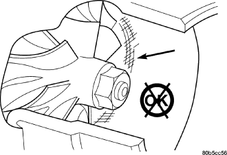
Visually inspect the turbocharger and exhaust manifold gasket surfaces. Replace stripped or eroded mounting studs.
1. Visually inspect the turbocharger for cracks. The following cracks are NOT acceptable:
- Cracks in the turbine and compressor housing that go completely through.
- Cracks in the mounting flange that are longer than 15 mm (0.6 in.).
- Cracks in the mounting flange that intersect bolt through-holes.
- Two cracks in the mounting flange that are closer than 6.4 mm (0.25 in.) together.
2. Visually inspect the impeller and compressor wheel fins for nicks, cracks, or chips.
3. Visually inspect the turbocharger compressor housing for an impeller rubbing condition. Replace the turbocharger if the condition exists.
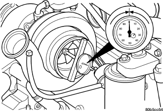
4. Measure the turbocharger axial end play:
a. Install a dial indicator. Zero the indicator at one end of travel.
b. Move the impeller shaft fore and aft and record the measurement. Allowable end play is 0.038 mm (0.0015 in.) MIN. and 0.089 mm (0.0035 in.) MAX. If the recorded measurement falls outside these parameters, replace the turbocharger assembly.
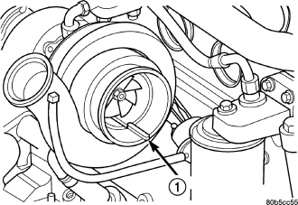
5. Measure the turbocharger bearing radial clearance:
a. Insert a narrow blade or wire style feeler gauge between the compressor wheel and the housing.
b. Gently push the compressor wheel toward the housing and record the clearance.
c. With the feeler gauge in the same location, gently push the compressor wheel away from the housing and again record the clearance.
d. Subtract the smaller clearance from the larger clearance. This is the radial bearing clearance.
e. Allowable radial bearing clearance is 0.326 mm (0.0128 in.) MIN. and 0.496 mm (0.0195 in.) MAX. If the recorded measurement falls outside these specifications, replace the turbocharger assembly.
INSTALLATION
1. For turbocharger installation (Refer to 9 - ENGINE/MANIFOLDS/INTAKE MANIFOLD - INSTALLATION).