INTEGRATED CONTROL UNIT (ICU)
DESCRIPTION

The Hydraulic Control Unit (HCU) (2) and the Antilock Brake Module (ABM) (1) used with this antilock brake system are combined (integrated) into one unit, which is called the Integrated Control Unit (ICU).
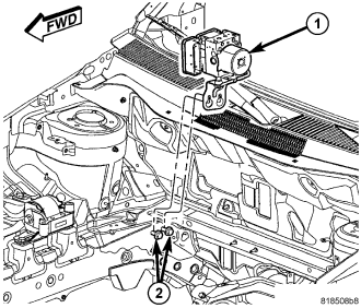
The ICU (1) is located in the engine compartment, mounted to the right side body frame rail near the strut tower.
The ABS with ESP and All-Speed Traction Control ICU consists of the following components: the ABM, 12 (build/decay) solenoid valves, two traction control solenoid valves, two hydraulic shuttle valves, valve block, fluid accumulators, a pump, and an electric pump/motor.
The replaceable components of the ICU are the HCU and the ABM. No attempt should be made to service any components of the HCU or ABM.
For additional information on the ABM, (Refer to 8 - ELECTRICAL/ELECTRONIC CONTROL MODULES/ANTILOCK BRAKE MODULE - DESCRIPTION). For additional information on the HCU, (Refer to 5 - BRAKES - ABS/HYDRAULIC/MECHANICAL/HCU (HYDRAULIC CONTROL UNIT) - DESCRIPTION).
OPERATION
For information of the ICU, refer to these individual components of the ICU:
- ANTILOCK BRAKE MODULE (ABM) (Refer to 8 - ELECTRICAL/ELECTRONIC CONTROL MODULES/ANTILOCK BRAKE MODULE - DESCRIPTION)
- HYDRAULIC CONTROL UNIT (HCU) (Refer to 5 - BRAKES - ABS/HYDRAULIC/MECHANICAL/HCU (HYDRAULIC CONTROL UNIT) - OPERATION)
DISASSEMBLY
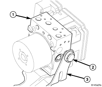
1. If the mounting bracket (3) needs to be removed from the ICU, remove the single mounting bolt (2), then slide the ICU's mounting pins out of the grommets in the bracket and remove the bracket.
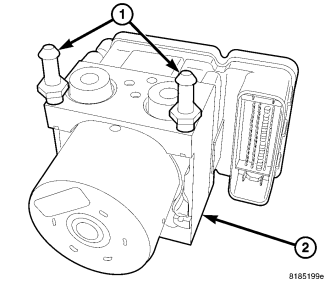
2. Remove the mounting pins from the ICU.
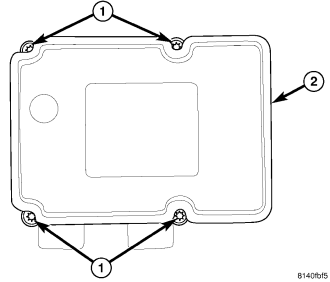
3. Remove the four screws (1) attaching the ABM (2) to the HCU.
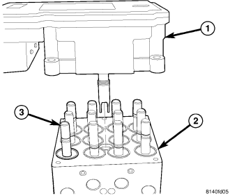
4. Separate the ABM (1) from the HCU (2).
ASSEMBLY
1. Clean any debris off the mating surfaces of the HCU and ABM.
CAUTION: When installing new O-rings or solenoid valve stem seals, do not use any type of lubricant.
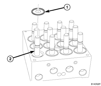
2. If the seals (1) on the solenoid valve stems (2) are not new, replace them all. Each of the solenoid valve stem seals must be new to keep out moisture and debris; do not reuse solenoid valve stem seals.
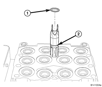
3. Replace the pump/motor connector O-ring (1) if it is not new. Be sure the O-ring is properly seated in the mounting groove (2).
4. Align components and install the ABM (1) on the HCU (2).
5. Install the four screws (1) attaching the ABM (2) to the HCU. Tighten the mounting screws to 2 N·m (17 in. lbs.).
6. If necessary, install the mounting pins (1) in the ICU (2) and tighten to 11 N·m (97 in. lbs.).
7. If the mounting bracket (3) needs to be installed on the ICU (1), install the mounting pins in the ICU as necessary and tighten to 11 N·m (97 in. lbs.). Insert the mounting pins into the grommets mounted in the bracket, then install the single mounting bolt (2). Tighten the mounting bolt to 11 N·m (97 in. lbs.).
8. Install the ICU in the vehicle. (Refer to 5 - BRAKES/HYDRAULIC/MECHANICAL/ICU (INTEGRATED CONTROL UNIT) - INSTALLATION)